Fox Red Labs / Builds / Screens and USB
Put colors and touch on a small screen
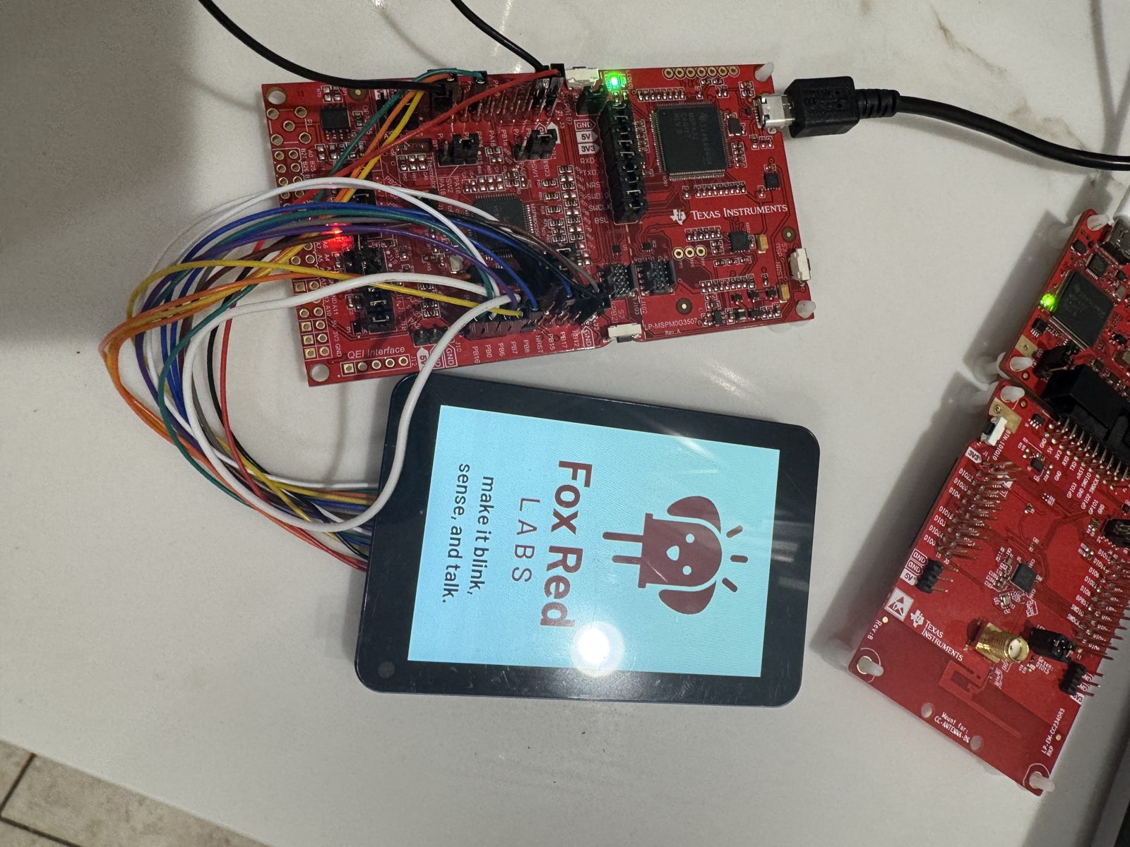
Wire a 3.5 inch touch screen to a LaunchPad kit with 11 jumper wires and run a 7.4 kB program that paints colors, bars and a dot under your finger.
MediumWiring needed1 evening
Parts and steps
You need
- LP-MSPM0G3507 LaunchPad development kit Buy the board
- Waveshare 3.5 inch capacitive touch LCD the screen and touch panel
- ELEGOO jumper wires 12 female-to-female as tested (11 are required); 13 with the optional MISO wire the wires from the screen to the LaunchPad header
- Micro-USB data cable power and programming
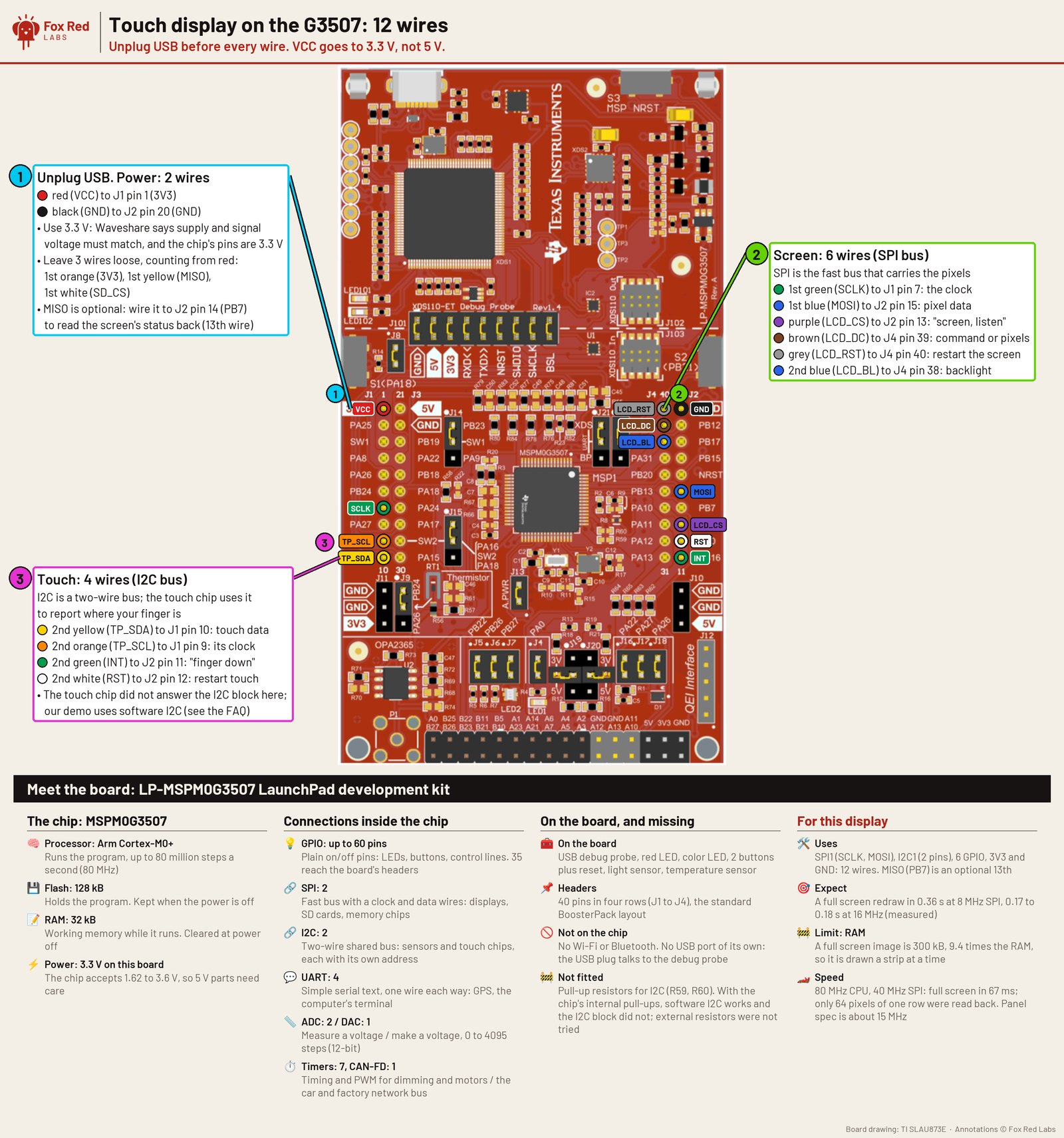
mspm0g3507/display-test/gen/ti_msp_dl_config.h). Signal and supply are both 3.3 V: the module's level translator takes the LaunchPad kit's 3V3, and nothing is driven at 5 V. No jumper on the LaunchPad moves. Full size.Pin table
| Display pin | LaunchPad pin | What it is | Needed |
|---|---|---|---|
| VCC pin (not the 3V3 pin) | J1 pin 1 (3V3) | power, 3.3 V only | required |
| GND | J2 pin 20 (GND) | ground | required |
| SCLK | J1 pin 7 (PB9) | screen clock, SPI1 | required |
| MOSI | J2 pin 15 (PB8) | screen data in, SPI1 | required |
| LCD_CS | J2 pin 13 (PB6) | screen chip select | required |
| LCD_DC | J4 pin 39 (PB1) | command or data | required |
| LCD_RST | J4 pin 40 (PB4) | screen reset | required |
| LCD_BL | J4 pin 38 (PA28) | backlight on | required |
| TP_SDA | J1 pin 10 (PB3) | touch data, software I2C | required |
| TP_SCL | J1 pin 9 (PB2) | touch clock, software I2C | required |
| TP_INT | J2 pin 11 (PB16) | touch interrupt. The program reads it once at start for a diagnostic value and finds touches by polling the touch chip, so the demo does not need it. Wired in the tested setup. | optional |
| TP_RST | J2 pin 12 (PB0) | touch reset | required |
| MISO | J2 pin 14 (PB7) | screen read-back; only to diagnose a dark screen | optional |
| 3V3 pin and SD_CS | not connected | the module's own 3V3 pin, which stays empty, and its SD card select | leave off |
Set up your computer once: 1 step. Done already? Start at step 2.
Install the tools once, all free.TERMINAL
Get CCStudio 21.0.1 from TI's CCStudio download page (1.9 GB download, 8.1 GB installed, free myTI login). It brings TI Arm Clang 5.1.1. Get the MSPM0 SDK 2.11.00.07 from TI's MSPM0 SDK download page (0.4 GB download, 2.2 GB installed). Then get xPack OpenOCD 0.12.0-7 from its GitHub release page (2 MB; the file
xpack-openocd-0.12.0-7-darwin-x64.tar.gzon an Intel Mac,...darwin-arm64.tar.gzon Apple Silicon) and unpack it in your home folder. Clone this repository into<repository folder>.You should see:
/Applications/ti/ccs2101/ccs/tools/compiler/ti-cgt-armllvm_5.1.1.LTS/bin/tiarmclang --versionprints 5.1.1, and the SDK folder/Applications/ti/mspm0_sdk_2_11_00_07exists.
With the LaunchPad unplugged, run the wires in the table above from the display to the header, power from the 3V3 pin only.BENCH
Leave the display's own 3V3 and SD_CS pins empty. A 13th wire, MISO, is optional and only for reading the screen's status back.
You should see: Every wire sits on the header row the picture shows; nothing is plugged into the display's 3V3 or SD_CS.
From the repository folder, build every variant of the display test into out/.TERMINAL
Replace
<repository folder>with the folder you cloned.Replace <repository folder> before you run this.
cd <repository folder>/mspm0g3507/display-test ./build.shYou should see: For each build, a line with the address of its
resresults struct and the program size. The demo,out/display_8mhz/display_8mhz.out, is 7.4 kB of flash and 648 bytes of RAM.Flash the 8 MHz demo with OpenOCD.TERMINAL
Replace
<probe serial>with your probe's serial number (read it withxdsdfu -e), and<repository folder>with your clone. The first command setsOCDto the folder you unpacked OpenOCD into.Replace <repository folder> and <probe serial> before you run this.
export OCD="$HOME/xpack-openocd-0.12.0-7" openocd -s "$OCD/openocd/scripts" -f <repository folder>/ports/bitnetmcu/openocd-mspm0.cfg -c "adapter serial <probe serial>" -c init -c "reset halt" -c "program out/display_8mhz/display_8mhz.out verify" -c "reset run" -c shutdownYou should see: OpenOCD finishes with the program verified, and the screen starts the demo: it fills red, green, blue, white and black, then draws eight color bars.
Touch the screen with a finger and drag it around.BENCH
You should see: A white dot is painted wherever you touch, and the board's red LED toggles on each touch.
Or hand it to a coding assistant
Paste this in a terminal. It hands off to an AI assistant.
git clone --depth 1 --filter=blob:none https://github.com/Fox-Red-Labs/fox-red-labs.git && cd fox-red-labs
./start.sh mspm0g3507 small-screen --assistant claudegit clone --depth 1 --filter=blob:none https://github.com/Fox-Red-Labs/fox-red-labs.git && cd fox-red-labs
py start.py mspm0g3507 small-screen --assistant claudeIt runs the steps above and reports what it saw.
Not Claude Code? Copy this prompt instead.
If something goes wrong
| Your tools live somewhere else | Change the SDK and CC lines at the top of build.sh in step 3. |
| You are not sure a wire is on the right pin | Count from the header's pin 1, the corner nearest the USB connector at J1. Check it against the table before plugging in. |
| The compiler or SDK is not found | Change the SDK and CC lines at the top of build.sh. |
| OpenOCD reports a CRC mismatch after the program step | See the OpenOCD CRC mismatch entry. |
| The screen stays dark or shows static with every wire right | See the screen stays dark entry. The chip-select gap or a wire is the usual cause, and LCD_BL on J4 pin 38 is the first wire to check. |
More troubleshooting
| Nothing follows the finger | Touch is not answering: the touch chip at address 0x38 entry has the two checks (software I2C pins, TP_RST). |
Every fix for this board: the FAQ.
What to build next
Every build. The code for all of them is in the GitHub repository.
Evidence and limitsA 3.5 inch touch screen on 11 wires (12 with the optional INT); a full-screen fill takes 67 ms at 40 MHz SPI. Ran on 1 board. Results, sources, timing and limits.
Expected result: The screen shows red, green, blue, white and black fills, then eight color bars. Then it paints a white dot under your finger and toggles the red LED on every touch. The whole program is 7.4 kB of flash and 648 bytes of RAM.
What this shows
- A TI LaunchPad kit with 32 kB of RAM drives a 320 x 480 SPI touch screen with 11 jumper wires (12 with the optional touch INT wire) and a small program from this repository. The screen's ID reads back as the ST7796S and the touch chip as the FT6336U.
- A full-screen fill of 300 kB takes 364.9 ms at 8 MHz SPI, 182.5 ms at 16 MHz, and 67.2 ms at 40 MHz SPI. The CPU runs at 80 MHz and frames are 16-bit. At every speed 64 pixels of one row were read back and matched.
- TI's MSPM0 SDK has no example for this screen or any TFT, so the driver is this repository's own.
What this does not establish, and limits
What this does not establish
- That the screen is right everywhere. At each speed only 64 pixels of one row were read back. The colors were not checked by eye at 16 MHz or faster.
- That 40 MHz SPI is safe in general. The chip's data sheet rates these standard-drive pins to 16 Mbit/s and the panel's allows about 15 MHz. It worked here on short wires; the margin may not hold elsewhere.
- The fills, bars and touch dots were seen by a person at the board and not recorded, so no photo or video of this exact program exists in the repository.
- A graphics library. LVGL runs on the same wiring, at 7 refreshes a second at 32 MHz and 15 to 19 at 80 MHz, using 25.1 kB of RAM. That is a different program, and its screen was not checked by eye.
Limits to keep in mind
- Chip select needs a 10 microsecond pause after it goes high between commands. Without it the screen drops the second of two back-to-back commands and never turns on. The program has the pause (
cs_gap()indisplay_test.c); a rewritten driver must keep it. - The touch chip answered only to software I2C on the same two pins. It did not answer to the chip's I2C block, so the program uses software I2C.
- One 320 x 480 frame at 16 bits is 300 kB, 9.4 times the chip's RAM, so drawing goes in strips and stored pictures are cut to 75 kB.
- The speed results need the separate
perfbuilds and a RAM dump through OpenOCD. The README's read command was assembled from the flash command and not re-run, so this build leaves it out.
Sources
Versions, sizes and timing
| Screen and touch | ST7796S over SPI1 (3-wire, 8 MHz in the demo) and FT6336U touch, software I2C at about 100 kHz, on a Waveshare module with a TXS0108E level translator | README notes |
|---|---|---|
| Full-screen fill | 364.9 ms at 8 MHz SPI; 182.5 ms at 16 MHz; 168.1 ms with 16-bit frames and DMA at 16 MHz; 134.4 ms at 20 MHz and 67.2 ms at 40 MHz SPI with the CPU at 80 MHz; 84 to 92% of what the SPI clock allows | README notes |
| Read-back check | 64 of 64 pixels of one row matched at every speed; no other pixels were checked | README notes |
| Program size | 7,592 bytes of flash (7.4 kB) and 648 bytes of RAM, from tiarmsize on display_8mhz.out | README notes |
| Start-up | 370 ms from power-up to screen ready with the usual init waits; 12 ms with the shortest waits the data sheet allows | README notes |
| Tools | Intel Mac, macOS 15.7; MSPM0 SDK 2.11.00.07; SysConfig 1.26.3; TI Arm Clang 5.1.1; xPack OpenOCD 0.12.0; 2026-10-06 | README notes |
Evidence
- 2026-10-06: after two fixes (a 10 microsecond chip-select gap and software I2C for the touch chip) the screen filled with color, showed bars, and drew a dot under the finger on each touch. A person at the board saw this. It was not recorded. MSPM0G3507 touch display notes
- Screen ID read back over MISO as 0x7796 (ST7796S); touch chip read as vendor 0x11, chip 0x64 (FT6336U), firmware 0x12 (observed, not saved). README notes
- Full-screen fill speeds were measured and saved: 364.9 ms at 8 MHz SPI, 67.2 ms at 40 MHz with an 80 MHz CPU clock.
Other boards
- MSPM33C321ACould work could work
- MSPM0L1306, CC2340R5, F2800137
- MSPM0G3519, CC1354P10could work
What the status words mean
Works ran here and did what it shouldCould work some of it ran; real porting effort is left; hover for whatNot for this chip the chip or its vendor software cannot; hover for why
Result grid
Works ran here and did what it shouldShould work it builds; only naming, packaging or build glue is in the way; hover for whichCould work some of it ran; real porting effort is left; hover for whatNot for this chip the chip or its vendor software cannot; hover for why
Experiments (5)
| Status | What was tried | Result |
|---|---|---|
| Works | Can a TI LP-MSPM0G3507 drive the Waveshare 3.5inch Capacitive Touch LCD? MSPM0 G3507, 2026-10-06 | Works: fills, bars and touch dots on 12 jumper wires (seen, not saved); a full-screen fill takes 0.36 s at 8 MHz SPI and 67 ms at 40 MHz SPI with an 80 MHz CPU. The line is memory: a full frame (300 kB) is 9.4 times... |
| Does the u8g2 display library compile for a TI C2000 LaunchPad (LAUNCHXL-F2800137), where a byte is 16 bits? LAUNCHXL-F2800137, 2026-10-08 | u8g2 2.37.1 compiles and links for the C28x when uint8_t is unsigned char (16 bits there): 19 kB of flash for u8x8 text plus one u8g2 font on an SSD1306. With C2000Ware's uint8_t (uint16_t) the fonts do not compile.... | |
| Works | Can the TI LP-AM263P decode H.264 video, with no video hardware and no operating system? AM263P, 2026-10-09 | h264bsd decodes the 30-frame 640x360 baseline test stream on one R5F at 400 MHz in 15.2M cycles per frame (26 frames per second, -Os), and all three checksums match the Mac's. It needed a 2 MB memory layout: the 3 MB... |
| Works | Can the TI LP-AM263P's PRU generate a parallel RGB display bus from on-chip RAM, and how does that compare with SPI and the AM263x's GPMC bus? AM263P, 2026-10-11 | The AM263P's PRU generates a parallel RGB565 bus from a frame buffer in on-chip RAM with no CPU time: 800x480 at 45.6 frames a second and 480x480 at 76.3 at a 22.2 MHz pixel clock, each frame's pixel sum matched at... |
| Works | Can an LP-MSPM0C1104 with 1 kB of RAM drive a 128 x 128 Sharp screen? MSPM0 C1104, 2026-10-20 | The 128 x 128 Sharp panel runs from the MSPM0 C1104 with no frame buffer: 4.9 kB of flash and 609 B of RAM (352 B of the stack used), the whole picture drawn and sent in 154 ms with 1-row bands and 41 ms with 16-row... |
Source files
Get the code and tell us how it wentThe clone command, the board folder with its AGENTS.md, reports from others, and the three report forms.
Get the code
Clone the repository and open the board's folder below. AGENTS.md is a plain text file of notes for AI coding assistants, and llms.txt at the root indexes the site for one.
git clone https://github.com/Fox-Red-Labs/fox-red-labs.git- LP-MSPM0G3507: folder
mspm0g3507/.- README: the board's lab notebook (what was run, in order)
- Notes for an AI coding assistant working in this repository: notes for an AI assistant; copy it into your own project if you use one
- FAQ: errors and fixes
Code is BSD-3-Clause, writing is CC BY 4.0; third-party folders keep their own licenses.
Built it? Tell us
Built this, or got stuck? Report it on GitHub with a few short answers. Your report shows here in your words, marked as yours. A failure that repeats on the bench gets its fix here.