Hardware / No radio: small chips / Step 4 of 5
LP-MSPM0G3519 (MSPM0G3519)
The MSPM0G3519 is a microcontroller in TI's MSPM0 family: 80 MHz Arm Cortex-M0+, 512 kB of flash, 128 kB of RAM.
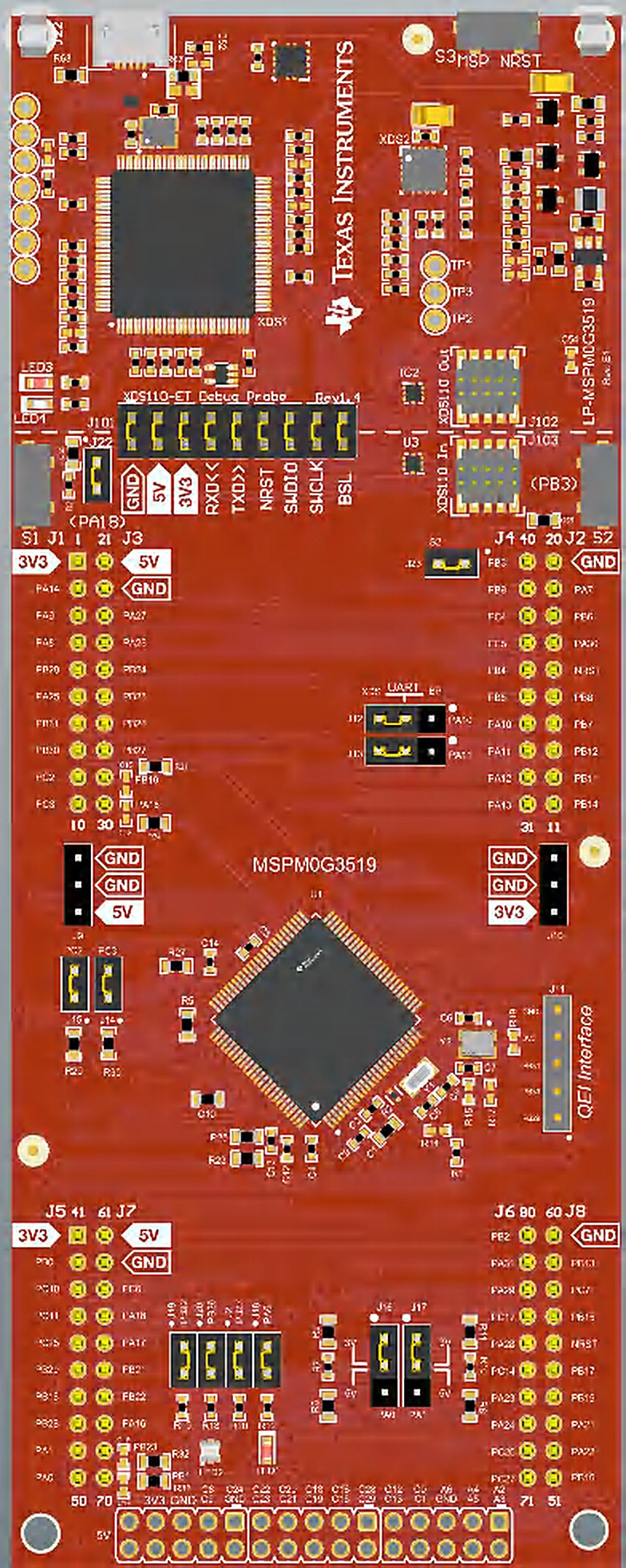
Quick facts
| Board | LP-MSPM0G3519 |
|---|---|
| Chip | MSPM0G3519 |
| Core | Cortex-M0+ |
| Clock | 80 MHz |
| Flash | 512 kB |
| RAM | 128 kB |
| Radio | None |
| Notable peripherals | dual-bank flash for OTA, plus 16 kB data flash; 2 x 12-bit 4 Msps ADC, up to 27 channels; 12-bit DAC; 3 comparators; math accelerator (DIV, SQRT, MAC, TRIG); AES-128/256, secure key storage |
| On-board debug probe | Built into the board |
| Zephyr board name | lp_mspm0g3519 |
| Where to buy | TI.com |
| Toolchains that ran | TI compilers, GCC, Zephyr, FreeRTOS, Arduino, MicroPython |
Get it running
First blink: 15.2 s from plug-in to a changed blink (terminal; 3 runs).
Plug the board into your computer with its USB cable. No driver to install.
In Chrome or Edge, open the browser bench and click Connect.
Pick Blink LED2 red: 150, 150, 150, 900 ms and click Flash. The page writes it to the board.
You should see: LED2 red (PB26) flashes twice, then pauses.
none listed in TI's example README
Install CCStudio 21.0.1 and the MSPM0 SDK 2.11. Free with a myTI login. On a Mac,
mac-setup/bootstrap.shin the repository does both after you sign in.File, Import Project, and pick:
/Applications/ti/mspm0_sdk_2_11_00_07/examples/nortos/LP_MSPM0G3519/driverlib/gpio_toggle_outputClick the green Debug button, then Resume.
You should see: an LED on the board blinks. The pattern is the delay in gpio_toggle_output.c: change it, build and flash again, and the blink changes.
Copy TI's blink example and build it.
cp -R <SDK>/examples/nortos/LP_MSPM0G3519/driverlib/gpio_toggle_output . ../mspm0-first-blink/mcu-bench/sdk-common/sdkmake.sh gpio_toggle_output/ticlangFlash it with UniFlash's command line.
<UniFlash>/dslite.sh --mode flash -c MSPM0G3519_<serial>.ccxml -e -f -v gpio_toggle_output/ticlang/gpio_toggle_output.out
Replace the parts in angle brackets. Run it from the terminal in VS Code, CCStudio or any IDE.
You should see: an LED on the board blinks. The pattern is the delay in gpio_toggle_output.c: change it, build and flash again, and the blink changes.
What works
- CoreMark: 182.73 (2.284 per MHz) (TI Arm Clang, bare metal, -O3; 80 MHz; 3 runs)
- Interrupt latency, pend to first handler line: 31 cycles (bare metal; 80 MHz; 3 runs)
- GPIO toggle: 1.0 cycles (80 MHz; 3 runs)
- Blink image size: 11.8 kB of flash, 4 kB of RAM (Zephyr)
- Room-occupancy AI model, one inference: 3.91 ms (-O3; 80 MHz)
- Control loop, trigger to new PWM value: 12.44 µs (-O2; 80 MHz; 3 runs)
- 256-point complex FFT: 0.918 ms (-O3; 80 MHz; 3 runs)
- AES-128: 9.33 cycles/B in hardware (TI Arm Clang, -O2; 80 MHz; 3 runs)
- RTOS task switch round trip: 6.99 µs (Zephyr; 80 MHz)
- Fastest ADC with DMA: 3.93 Msps (32 MHz)
Download every result for this board (CSV), or compare it on this board on the Benchmarks page.
Projects and ports that ran here
- Run a small AI model on the chip: 3.91 ms per answer, fastest build on this chip
- Measure how fast a chip runs: 183 CoreMark score at the board's top clock
- Build and flash from the terminal: 5.5 s TI examples built
- Run Arduino's own sketches on a TI chip: Blink and AnalogReadSerial run unchanged on Zephyr main
- Retro games on a LaunchPad: 2048 played on the Waveshare 3.5 inch panel with working touch; CHIP-8 test ROMs and a ZX Spectrum BASIC prompt run
- Post-quantum on every board: Both algorithms on a Cortex-M0+ at 80 MHz with no cycle counter
- Audio and video codecs on a LaunchPad: MP3 decodes bit-exact on the Cortex-M0+ at 80 MHz, but at 9.84 times real time, so it does not keep up
- 2048 and Minesweeper on the LP-MSPM0G3519 with a 3.5 inch touch display Works: 2048 and Minesweeper run on the MSPM0 G3519 with a 3.5 inch touch display.
- Arduino sketches on the LP-EM-CC2340R5 and LP-MSPM0G3519 through the Zephyr-based core: Blink and AnalogReadSerial Works: Arduino's stock Blink and AnalogReadSerial run unchanged on the CC2340R5 and MSPM0 G3519 through the Zephyr-based core.
- CHIP-8 interpreter and the chip8-test-suite on the LP-MSPM0G3519 touch panel Works: A CHIP-8 interpreter runs the chip8-test-suite ROMs on the MSPM0 G3519 touch panel, with the frame buffer equal to the host's for five of six.
- ESP32-BLE-Gamepad (a Bluetooth HID gamepad library) on TI, ST and C2000 boards Works: The ESP32-BLE-Gamepad descriptor and reports match the library's output byte for byte on four boards, and 15 of 15 button changes from the CC2340R5 reached a Mac as gamepad reports.
- liblc3 (LC3, the Bluetooth LE Audio codec) on the LP-MSPM33C321A and LP-MSPM0G3519 Works: liblc3 (LC3, the Bluetooth LE Audio codec) encodes and decodes frames on the MSPM33 C321A with the CRC-32 of every frame equal to the Mac build.
- MicroPython 1.29.0 on the LP-MSPM0G3519 and LP-MSPM0G3507 Works: A new MicroPython port boots on the MSPM0 G3519 with the MicroPython banner and drives a 3.5 inch touch screen from Python.
- minimp3 MP3 decoder on the LP-MSPM33C321A and LP-MSPM0G3519 Works: minimp3 decodes MP3 clips bit-exact against the Mac on the MSPM33 C321A and MSPM0 G3519.
- minmea GPS sentence parser on MSPM0 Works: minmea, an NMEA GPS parser, runs on the MSPM0 G3519 with its files unchanged and a 21-line shim for one missing call.
- Peanut-GB Game Boy emulator on MSPM0 and MSPM33 Works: Peanut-GB plays Tobu Tobu Girl on the MSPM33 C321A with the Educational BoosterPack screen at the console's own speed.
- Raspberry Pi Pico SDK examples on the LP-MSPM0G3519 Works: Raspberry Pi pico-examples (serial hello, I2C bus scan, blink, PWM fade, ADC read) run unchanged on the MSPM0 G3519 over a thin layer on DriverLib.
- Renesas FSP examples (UART, ADC, I2C, GPT timer) on the LP-MSPM0G3519 Works: Four of five Renesas FSP examples (FSP is Renesas's driver layer) run on the MSPM0 G3519 on a layer that maps FSP calls onto DriverLib, TI's register-level driver library.
- STM32 UART DMA receive with idle-line interrupt (MaJerle stm32-usart-uart-dma-rx-tx) on TI boards Works: MaJerle's STM32 UART DMA example answers every test packet at 115200 baud on the MSPM0 G3519, G5187, L1306, C1104 and MSPM33C321A.
- STM32 UART Xmodem bootloader (ferenc-nemeth/stm32-bootloader) on the LP-MSPM0G3519 Works: ferenc-nemeth's STM32 Xmodem bootloader takes an application over UART on the MSPM0 G3519, writes it to flash and jumps to it.
- uLisp Lisp interpreter on the LP-MSPM0G5187, LP-MSPM0G3507 and LP-MSPM0G3519 Works: uLisp, an Arduino sketch, gives a Lisp prompt on the MSPM0 G5187's serial port: 19 of 19 REPL (type-and-run loop) checks pass.
- wasm3 (WebAssembly interpreter) on the LP-MSPM0G3519, LP-MSPM0G3507 and LP-MSPM33C321A Works: wasm3 runs a WebAssembly module on the MSPM0 G3519 and prints PASS on the serial line.
- Arduboy2-compatible layer and three open-source games on MSPM0 and MSPM33 Could work: Snake, TileWorld and Crate Confusion build unchanged against an Arduboy2-compatible layer for four kits, and Snake draws on the MSPM33 C321A's Educational BoosterPack screen.
- BoosterPack drivers (Educational MKII, Sharp128, Audio, Sensors MKII, NPU DSP) on LaunchPad kits of other families Could work: Portable C cores for BoosterPacks ran: the Educational pack on the MSPM0 L1306 and MSPM33 C321A, the Sharp128 panel on the MSPM0 C1104, the Audio pack on the AM13E230 and the Sensors pack on the MSPM0 G5187.
- ZX Spectrum 48K (floooh/chips Z80 core) on the LP-MSPM0G3519 touch panel Could work: A ZX Spectrum 48K runs on the MSPM0 G3519 touch panel, and its screen memory equals the host machine's after 400 frames.
Want wireless? Try the LP-EM-CC2340R5 for Bluetooth, Zigbee or Thread or the LP-EM-CC35X1 for Wi-Fi.
Fixes
- If you see Zephyr blinky builds and flashes, nothing blinks; program counter at
z_SysNmiOnReset,SYSCTL.NMIIIDXreads 6, pulse nRST after the DSLite flash (mspm0_board_resetin OpenOCD); the image then runs (portability/arduino/zephyr/README.md, 2026-10-25). - If you see Zephyr prints
FLASH: 256 KBandRAM: 64 KB, size a Zephyr application for 256 kB flash and 64 kB RAM. - If you see
adc12_internal_temp_sensor_mathaclprints about 507, treat the raw code as relative; cause unknown. - If you see UART0 loopback PA10 to PA11 fails at 5.5 and 6.0 Mbaud, sends nothing at 12 Mbaud, use 9,600 baud to 5.33 Mbaud or 6.4 to 10.67 Mbaud, and test your exact rate.
- If you see a Zephyr peripheral pin stays low (or does the wrong thing) although the peripheral runs, for example PWM on PB27, define the pin group yourself from SysConfig's
MSPM0G351X.json. - If you see Zephyr main on this board: a second interrupt edge mode on a pin fires on both edges, and PWM duty comes out inverted, clear the pin's two polarity bits before attaching; write
period - pulse. - If you see the first I2C transfer to the Waveshare panel's FT6336U fails right after boot, hold the reset low 5 ms, release it, wait 400 ms before the first transfer.
- If you see an I2C read returns the ID, then the next write never completes and the bus stays busy, leave the ACK bit off on reads so the controller sends the NACK that ends them.
For AI assistants
Point your assistant at this board's AGENTS.md (build, flash and fix notes) and the repository's llms.txt (the index).
Sources: mspm0g3519/README.md, mspm0g3519/AGENTS.md, mspm0g3519/FAQ.md, data/results/mspm0g3519.csv, site/data/portfolio.json, site/data/projects.json, site/data/ports.json.