Pins are drawn on TI's board drawing; the source is in the repo next to the README. Open full size
Loop 2: the chip texts itself over UART
You need
- LP-MSPM0G3507 LaunchPad development kit: TI's 80 MHz Arm Cortex-M0+ board with 128 kB flash and 32 kB RAM, a built-in debugger, three buttons, two LEDs (one RGB) and light and temperature sensors.
- ELEGOO jumper wires (120-piece pack): Male and female breadboard wires for connecting anything to anything.
Wiring
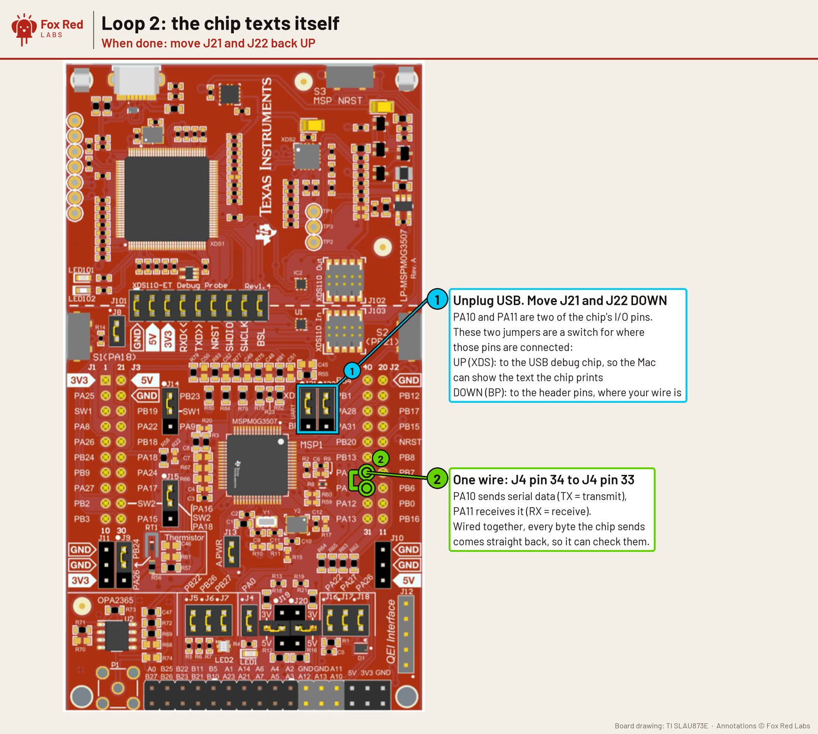
- Unplug USB
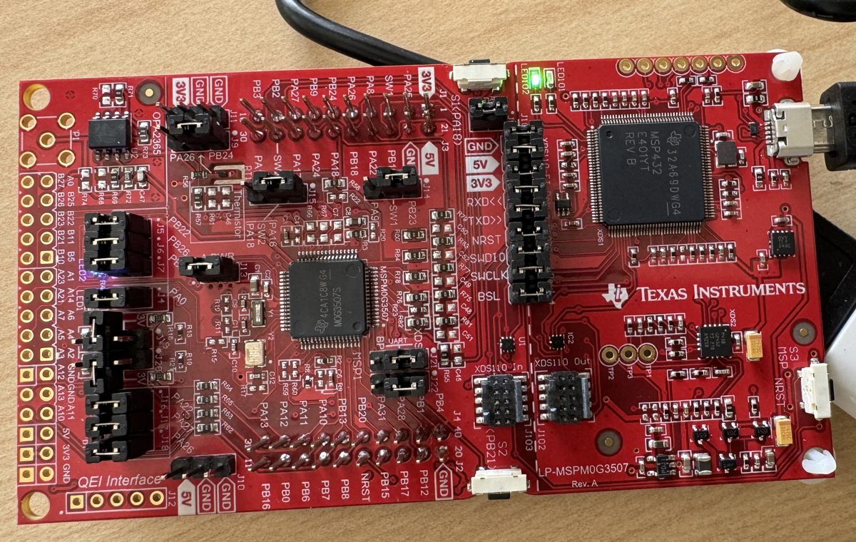
- Move jumpers J21 and J22 down, from XDS to BP, so the UART pins reach the header instead of the USB chip
- One wire from J4 pin 34 (PA10, transmit) to J4 pin 33 (PA11, receive)
- When done, move J21 and J22 back up or the board's serial window stays silent
What was measured
- All 2 kB right at every speed from 9.6 kbaud to 4.5 Mbaud and again from 6.4 to 10.67 Mbaud
- Dead band at 5 to 6 Mbaud: 5 Mbaud gets 39 of 2,048 right and 6 Mbaud gets 1,921, which is 94%; 12 Mbaud sends nothing. The MSPM0 L1306 shows the same dead band. The cause was not found; TI does not document the baud divider's behavior at those settings
- If your serial window goes silent after moving J21 and J22, move them back to XDS. TI's example README says only to jumper PA10 to PA11 and does not mention J21 and J22
Versions: MSPM0 SDK 2.11.00.07, TI Arm Clang 5.1.1; measured 2026-10-06.
Next: Find the cause of the dead band: try the fractional baud divider settings one at a time.
How to repeat it: Jumper wires on the LP-MSPM0G3507: three loops to start. Errors and fixes: FAQ. Numbers from Loop tests: the G3507 measuring itself through two jumper wires.