Hardware / No radio: small chips / Step 5 of 5
LP-MSPM0G5187 (MSPM0G5187)
The MSPM0G5187 is a microcontroller in TI's MSPM0 family: 80 MHz Arm Cortex-M0+, 128 kB of flash, 32 kB of RAM.
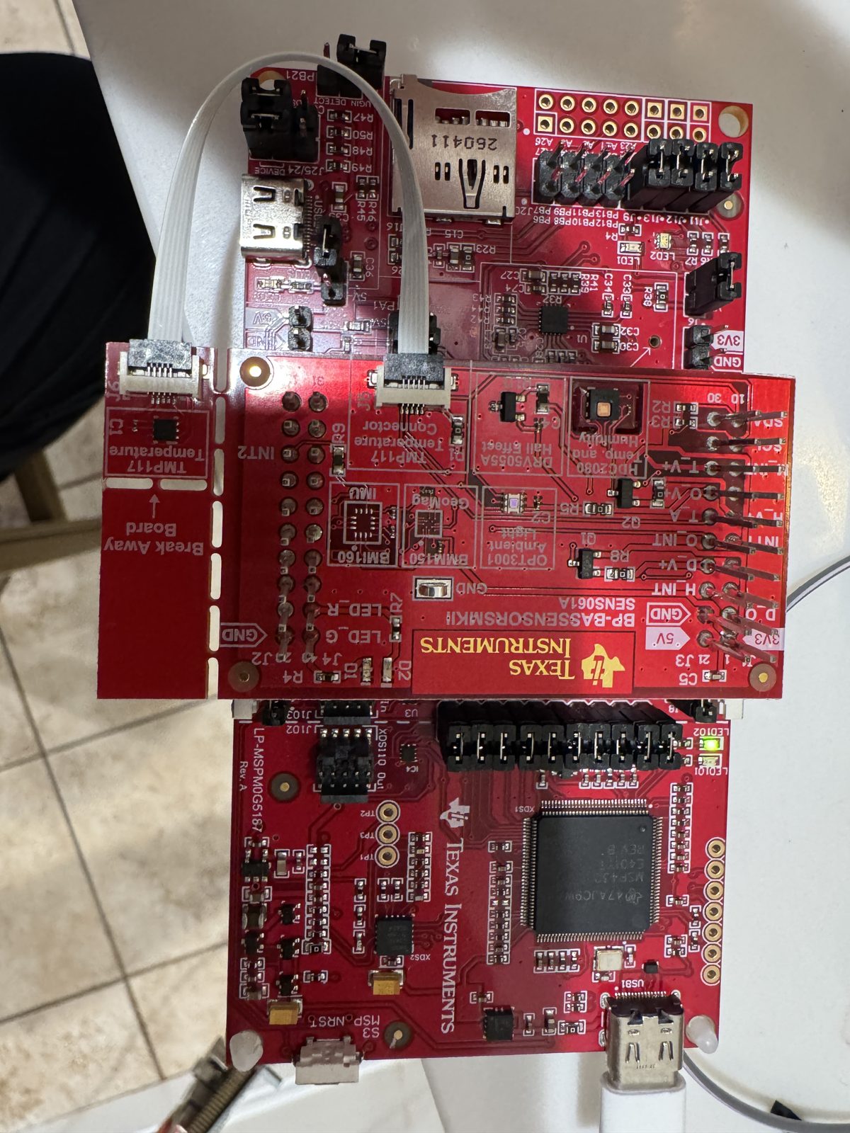
Quick facts
| Board | LP-MSPM0G5187 |
|---|---|
| Chip | MSPM0G5187 |
| Core | Cortex-M0+ |
| Clock | 80 MHz |
| Flash | 128 kB |
| RAM | 32 kB |
| Radio | None |
| Notable peripherals | TinyEngine NPU, 2.56 GOPS at 80 MHz (CNN, 8/4/2-bit weights); USB 2.0 full speed, crystal-less device mode; I2S/TDM audio; 12-bit 1.6 Msps ADC, up to 26 channels; AES with GCM/CCM; board adds microphone, audio ADC, microSD slot |
| On-board debug probe | Built into the board |
| Where to buy | TI.com |
| Toolchains that ran | TI compilers, GCC, Zephyr, FreeRTOS |
Get it running
First blink: 13.2 s from plug-in to a changed blink (terminal; 2 runs).
Plug the board into your computer with its USB cable. No driver to install.
In Chrome or Edge, open the browser bench and click Connect.
Pick Blink LED2 red: 150, 150, 150, 900 ms and click Flash. The page writes it to the board.
You should see: LED2 red (PA17) flashes twice, then pauses.
J12 [2:1] populated for red; J13 [2:1] populated for green; J11 [2:1] populated for blue (TI's example README)
Install CCStudio 21.0.1 and the MSPM0 SDK 2.11. Free with a myTI login. On a Mac,
mac-setup/bootstrap.shin the repository does both after you sign in.File, Import Project, and pick:
/Applications/ti/mspm0_sdk_2_11_00_07/examples/nortos/LP_MSPM0G5187/driverlib/gpio_toggle_outputClick the green Debug button, then Resume.
You should see: an LED on the board blinks. The pattern is the delay in gpio_toggle_output.c: change it, build and flash again, and the blink changes.
Copy TI's blink example and build it.
cp -R <SDK>/examples/nortos/LP_MSPM0G5187/driverlib/gpio_toggle_output . ../mspm0g3507/mcu-bench/sdk-common/sdkmake.sh gpio_toggle_output/ticlangFlash it with UniFlash's command line.
<UniFlash>/dslite.sh --mode flash -c MSPM0G5187_<serial>.ccxml -e -f -v -u gpio_toggle_output/ticlang/gpio_toggle_output.out
Replace the parts in angle brackets. Run it from the terminal in VS Code, CCStudio or any IDE.
You should see: an LED on the board blinks. The pattern is the delay in gpio_toggle_output.c: change it, build and flash again, and the blink changes.
What works
- CoreMark: 182.79 (2.285 per MHz) (TI Arm Clang, bare metal, -O3; 80 MHz; 3 runs)
- Board-to-board radio round trip: 7.1 ms (bare metal, Zephyr; 80 MHz; 11 runs)
- Radio command to state change, median: 3,010 ms (80 MHz)
- Interrupt latency, pend to first handler line: 36 cycles (bare metal; 80 MHz; 3 runs)
- GPIO toggle: 1.0 cycles (-O2; 80 MHz; 3 runs)
- Blink image size: 528 B of flash, 256 B of RAM (bare metal)
- Room-occupancy AI model, one inference: 1.292 ms (-O2; 80 MHz; 3 runs)
- Control loop, trigger to new PWM value: 26.27 µs (-O2; 80 MHz; 3 runs)
- 256-point complex FFT: 0.918 ms (-O3; 80 MHz; 3 runs)
- AES-128: 9.39 cycles/B in hardware (TI Arm Clang, -O2; 80 MHz; 3 runs)
Download every result for this board (CSV), or compare it on this board on the Benchmarks page.
Projects and ports that ran here
- Run a small AI model on the chip: 1.29 ms per answer on the neural network accelerator (plain C: 3.9 ms)
- Measure how fast a chip runs: 183 CoreMark score at the board's top clock
- Send sensor readings between two boards by radio: The sender: temperature, humidity and light every 1.04 s at 915 MHz, 50 kbps 2-GFSK; 21,658 of 21,658 received, 0 checksum errors
- Post-quantum on every board: ML-KEM-768 only: 24.9, 29.8 and 36.4 ms at -Os in 14 to 18 kB of stack
- A Lisp prompt on a LaunchPad: 19 of 19 REPL checks and 5 benchmark runs pass; `(tak 18 12 6)` takes 7.5 s at 80 MHz; the image is 98.8 kB of flash and 23.1 kB of RAM
- Walkie-talkie over a 915 MHz radio: Receives the spoken message: 122 of 122 frames with a good checksum, 121 exactly as sent, a median 99.2 ms from the computer to the computer
- Sub-1 GHz home radio demos: Runs the fox hunt beacon, the key finder handset and the house node over 915 MHz: 64 of 64 beacons, 10 of 10 rings in 21 ms
- Fixed-weight DSP (FIR, filter bank, DFT) on the LP-MSPM0G5187 Works: A 64-tap FIR filter runs on the MSPM0 G5187's NPU (its neural-network accelerator), compiled with NNC, TI's neural-network compiler, 29.7 times faster than the same graph on the CPU, with byte-for-byte equal output.
- Peanut-GB Game Boy emulator on MSPM0 and MSPM33 Works: Peanut-GB plays Tobu Tobu Girl on the MSPM33 C321A with the Educational BoosterPack screen at the console's own speed.
- STM32 UART DMA receive with idle-line interrupt (MaJerle stm32-usart-uart-dma-rx-tx) on TI boards Works: MaJerle's STM32 UART DMA example answers every test packet at 115200 baud on the MSPM0 G3519, G5187, L1306, C1104 and MSPM33C321A.
- Sub-1 GHz CC1407P radio on an LP-MSPM0G5187, heard by an LP-CC1354P10-1 Works: TI's CC1407P sub-1 GHz radio driver runs unchanged on the MSPM0 G5187, and a CC1354P10-1 receives its packets: 21,658 of 21,658.
- uLisp Lisp interpreter on the LP-MSPM0G5187, LP-MSPM0G3507 and LP-MSPM0G3519 Works: uLisp, an Arduino sketch, gives a Lisp prompt on the MSPM0 G5187's serial port: 19 of 19 REPL (type-and-run loop) checks pass.
- Arduboy2-compatible layer and three open-source games on MSPM0 and MSPM33 Could work: Snake, TileWorld and Crate Confusion build unchanged against an Arduboy2-compatible layer for four kits, and Snake draws on the MSPM33 C321A's Educational BoosterPack screen.
- BoosterPack drivers (Educational MKII, Sharp128, Audio, Sensors MKII, NPU DSP) on LaunchPad kits of other families Could work: Portable C cores for BoosterPacks ran: the Educational pack on the MSPM0 L1306 and MSPM33 C321A, the Sharp128 panel on the MSPM0 C1104, the Audio pack on the AM13E230 and the Sensors pack on the MSPM0 G5187.
- Wiring demo: Six sensors on one BoosterPack: what you get, what is read, how accurate it is: Humidity and temperature (HDC2080): 24.3 to 24.5 C and 37.4 to 37.8 percent RH
Want wireless? Try the LP-EM-CC2340R5 for Bluetooth, Zigbee or Thread or the LP-EM-CC35X1 for Wi-Fi.
Fixes
- If you see "OK Kilby" never lights the LED, stack a BOOSTXL-EDUMKII, or use the I2S port in
mspm0g5187/wakeword/(its microphone run needs the radio wires off header J20). - If you see the program waits forever on
tvmgen_default_finished, flash with DSLite so the image starts itself, then halt and read without a reset. - If you see
adc12_monitor_supplyreads codes of 540 to 674 that drift, do not use this example to read the supply on this board; the G3507 reads a steady 1,796 to 1,797. - If you see Debugger shows
SYSCFG_DL_SYSCTL_CLK_initand nothing happens after a good flash, skip those examples. - If you see
GCONV layer NOT offloaded to TI-NPU, accept it. - If you see
scan=nonefrom the Sensors BoosterPack, unplug USB, press the BoosterPack straight down so its pin 1 (3V3) sits in J1 pin 1, replug. - If you see
tmp117=nonewith the ribbon cable in, try a second cable or another LaunchPad. - If you see I2C scan shows every address from 08 to 77 after plugging the flat cable, unplug USB, turn the cable around, push both ends in and press the latches flat.
For AI assistants
Point your assistant at this board's AGENTS.md (build, flash and fix notes) and the repository's llms.txt (the index).
Sources: mspm0g5187/README.md, mspm0g5187/AGENTS.md, mspm0g5187/FAQ.md, data/results/mspm0g5187.csv, site/data/portfolio.json, site/data/projects.json, site/data/ports.json.