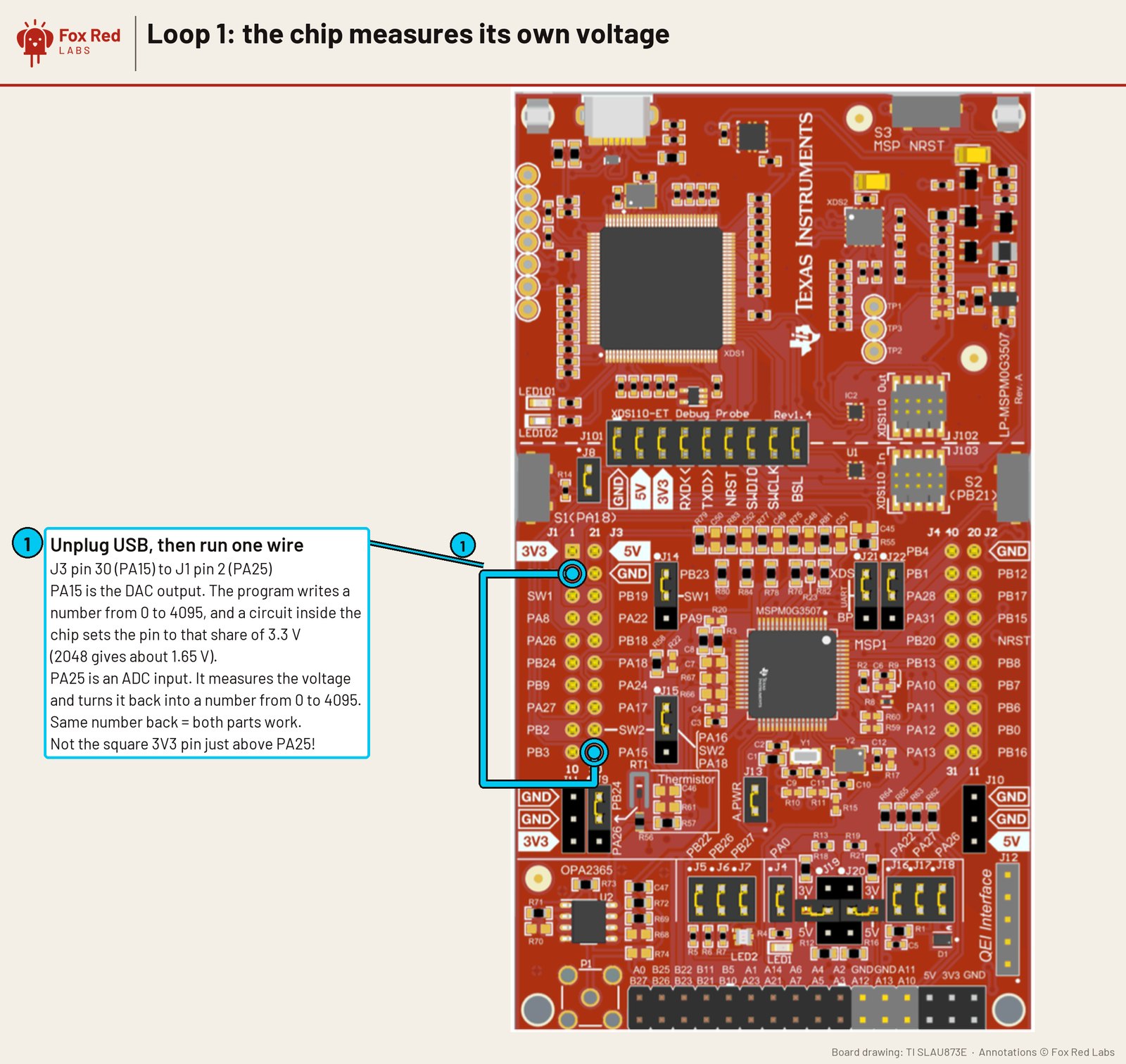
Pins are drawn on TI's board drawing; the source is in the repo next to the README. Open full size
Loop 1: the chip's voltage maker into its own voltmeter
You need
- LP-MSPM0G3507 LaunchPad development kit: TI's 80 MHz Arm Cortex-M0+ board with 128 kB flash and 32 kB RAM, a built-in debugger, three buttons, two LEDs (one RGB) and light and temperature sensors.
- ELEGOO jumper wires (120-piece pack): Male and female breadboard wires for connecting anything to anything.
Wiring
- Unplug USB
- One wire from J3 pin 30 (PA15, the DAC output) to J1 pin 2 (PA25, an ADC input). J1 pin 2 sits under the square 3V3 pad
- No jumpers move
What was measured
- Gain error 0.34%, gain 0.99656, across 257 DAC steps, 16 ADC reads each, both against the 3.3 V supply
- The ADC reads 0 to 13.5 codes low, averaging 7.2 codes or 0 to 11 mV; noise 1.56 codes, about 9.6 effective bits
Versions: MSPM0 SDK 2.11.00.07, TI Arm Clang 5.1.1; measured 2026-10-06.
Next: The same loop through the op-amp, and a second ADC channel.
How to repeat it: Jumper wires on the LP-MSPM0G3507: three loops to start. Errors and fixes: FAQ. Numbers from Loop tests: the G3507 measuring itself through two jumper wires.