Fox Red Labs / Builds / Smart home and radio
Sub-1 GHz home radio demos
A beacon you hunt by signal strength, a key finder you ring, and a house node for the mailbox, doorbell, panic button and keep-close tag. One pair of radios runs all three.
HardWiring needed
Parts and steps
Which version
You need
- LP-MSPM0G5187 LaunchPad development kit the CC1407P's host
- BP-CC1407P-9-FE sub-1 GHz radio BoosterPack plug-in module the sub-1 GHz radio
- LP-CC1354P10-1 LaunchPad development kit the other radio
- ELEGOO jumper wires x8 radio to the LaunchPad's J20 header
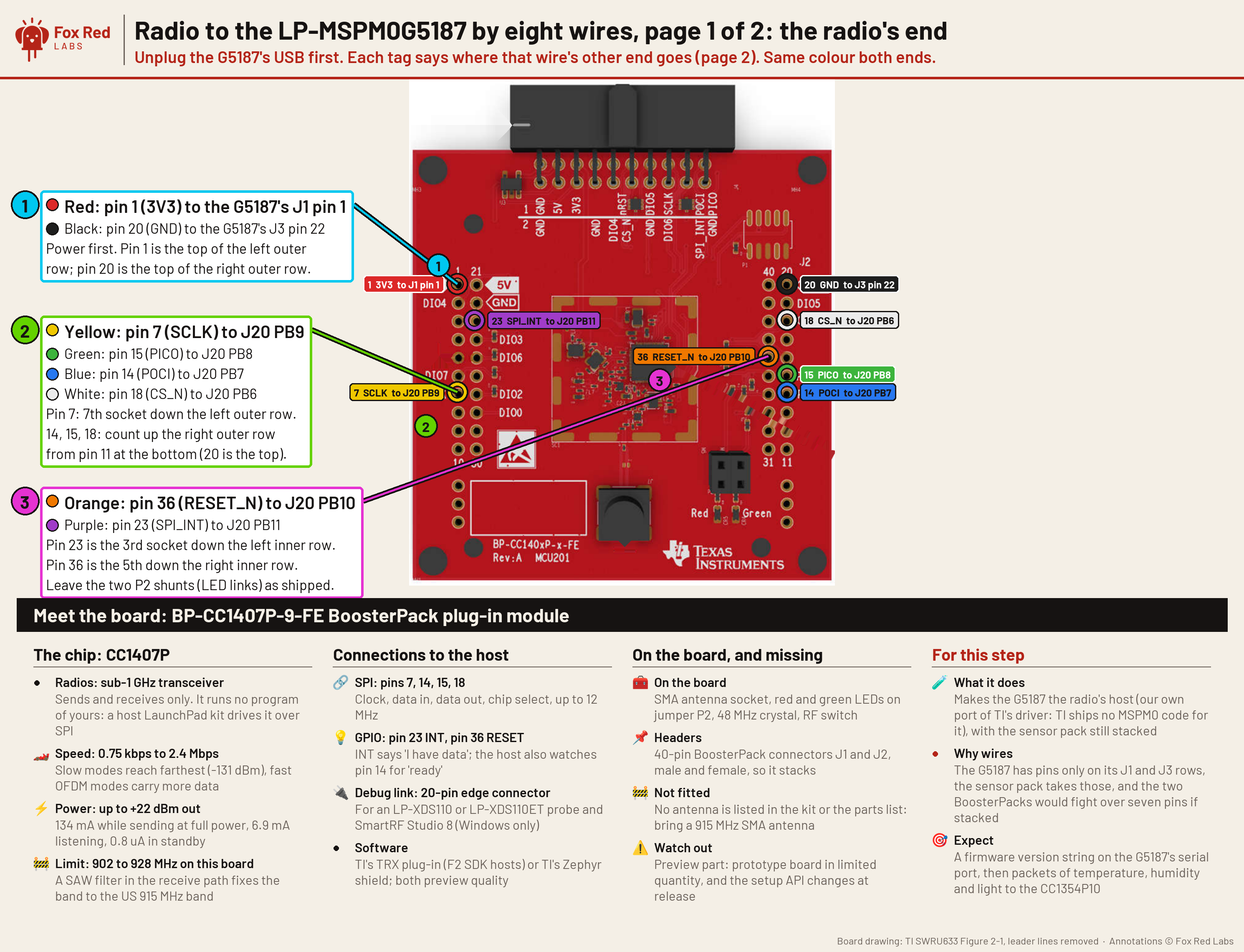
Pin table
| Radio pin | LaunchPad pin | What it is | Needed |
|---|---|---|---|
| Radio pin 1 (3V3) | J1 pin 1 (3V3) | power | required |
| Radio pin 20 (GND) | J3 pin 22 (GND) | ground | required |
| Radio pin 7 (SCLK) | J20 PB9 | SPI clock | required |
| Radio pin 15 (PICO) | J20 PB8 | data into the radio | required |
| Radio pin 14 (POCI) | J20 PB7 | data out of the radio | required |
| Radio pin 18 (CS_N) | J20 PB6 | chip select | required |
| Radio pin 36 (RESET_N) | J20 PB10 | radio reset | required |
| Radio pin 23 (SPI_INT) | J20 PB11 | radio says it has data | required |
Wire the radio to the LaunchPad.BENCH
With USB unplugged, screw the 915 MHz antenna onto the radio board's SMA socket and join the radio to the MSPM0 G5187's J20 header with the eight wires in the table. Plug the other LaunchPad into the Mac.
You should see: Each wire's other end is on the pin in the table.
Build the CC1407P side.TERMINAL
Build
radio_lab, which turns the MSPM0 G5187 into a radio driven by text commands on its serial port.RADIO_APP=radio_lab mspm0g5187/radio/build.shYou should see: The script ends with
image: mspm0g5187/radio/out/radio_lab.out.Build the partner side on the CC1354P10.TERMINAL
Follow the Build section of
cc1354p10/radio-rx/README.mdto get the F2 SDK libraries and therfPacketRxexample, then buildpartner.cas that README describes, with the 2-GFSK 50 kbps setting.You should see: The build leaves
rfPacketRx.hex, about 29 kB.Flash both boards.TERMINAL
Put each probe's serial in its
.ccxml(xdsdfu -elists them). Flashradio_lab.outto the MSPM0 G5187 andrfPacketRx.hexto the CC1354P10, then start the CC1354P10 withxds110reset.Replace <serial> before you run this.
/Applications/ti/uniflash_9.6.0/dslite.sh --mode flash -c mspm0g5187/MSPM0G5187_<serial>.ccxml -e -f -v mspm0g5187/radio/out/radio_lab.outYou should see: Both boards answer on their serial ports.
Run the fox hunt.TERMINAL
Set the two serial ports, then run the demo. The CC1407P beacon steps its power from +14 to -30 dBm in 8 steps, standing in for walking away; the CC1354P10 reports each step as hot, warm, cool or cold.
Replace <G5187 serial> and <partner probe serial> before you run this.
LAB_G=/dev/cu.usbmodem<G5187 serial>1 LAB_P=/dev/cu.usbmodem<partner probe serial>1 python3 mspm0g5187/radio/demos.py foxYou should see: All 8 steps are heard, and the hunter's call moves from hot to cool.
You need
- LP-MSPM0G5187 LaunchPad development kit the CC1407P's host
- BP-CC1407P-9-FE sub-1 GHz radio BoosterPack plug-in module the sub-1 GHz radio
- LP-CC1354P10-1 LaunchPad development kit the other radio
- ELEGOO jumper wires x8 radio to the LaunchPad's J20 header
Pin table
| Radio pin | LaunchPad pin | What it is | Needed |
|---|---|---|---|
| Radio pin 1 (3V3) | J1 pin 1 (3V3) | power | required |
| Radio pin 20 (GND) | J3 pin 22 (GND) | ground | required |
| Radio pin 7 (SCLK) | J20 PB9 | SPI clock | required |
| Radio pin 15 (PICO) | J20 PB8 | data into the radio | required |
| Radio pin 14 (POCI) | J20 PB7 | data out of the radio | required |
| Radio pin 18 (CS_N) | J20 PB6 | chip select | required |
| Radio pin 36 (RESET_N) | J20 PB10 | radio reset | required |
| Radio pin 23 (SPI_INT) | J20 PB11 | radio says it has data | required |
Wire the radio to the LaunchPad.BENCH
With USB unplugged, screw the 915 MHz antenna onto the radio board's SMA socket and join the radio to the MSPM0 G5187's J20 header with the eight wires in the table. Plug the other LaunchPad into the Mac.
You should see: Each wire's other end is on the pin in the table.
Build the CC1407P side.TERMINAL
Build
radio_lab, which turns the MSPM0 G5187 into a radio driven by text commands on its serial port.RADIO_APP=radio_lab mspm0g5187/radio/build.shYou should see: The script ends with
image: mspm0g5187/radio/out/radio_lab.out.Build the partner side on the CC1354P10.TERMINAL
Follow the Build section of
cc1354p10/radio-rx/README.mdto get the F2 SDK libraries and therfPacketRxexample, then buildpartner.cas that README describes, with the 2-GFSK 50 kbps setting.You should see: The build leaves
rfPacketRx.hex, about 29 kB.Flash both boards.TERMINAL
Put each probe's serial in its
.ccxml(xdsdfu -elists them). Flashradio_lab.outto the MSPM0 G5187 andrfPacketRx.hexto the CC1354P10, then start the CC1354P10 withxds110reset.Replace <serial> before you run this.
/Applications/ti/uniflash_9.6.0/dslite.sh --mode flash -c mspm0g5187/MSPM0G5187_<serial>.ccxml -e -f -v mspm0g5187/radio/out/radio_lab.outYou should see: Both boards answer on their serial ports.
Ring the handset.TERMINAL
Set the two serial ports, then run the demo. The base sends "ring" 10 times; the CC1407P answers with the signal it heard and blinks its LEDs.
Replace <G5187 serial> and <partner probe serial> before you run this.
LAB_G=/dev/cu.usbmodem<G5187 serial>1 LAB_P=/dev/cu.usbmodem<partner probe serial>1 python3 mspm0g5187/radio/demos.py ringYou should see: Ten rings, ten answers, and the handset's LEDs blink each time.
You need
- LP-MSPM0G5187 LaunchPad development kit the CC1407P's host
- BP-CC1407P-9-FE sub-1 GHz radio BoosterPack plug-in module the sub-1 GHz radio
- LP-CC1354P10-1 LaunchPad development kit the other radio
- ELEGOO jumper wires x8 radio to the LaunchPad's J20 header
- BP-BASSENSORSMKII Sensors BoosterPack plug-in module the light sensor (mailbox) and the buttons
Pin table
| Radio pin | LaunchPad pin | What it is | Needed |
|---|---|---|---|
| Radio pin 1 (3V3) | J1 pin 1 (3V3) | power | required |
| Radio pin 20 (GND) | J3 pin 22 (GND) | ground | required |
| Radio pin 7 (SCLK) | J20 PB9 | SPI clock | required |
| Radio pin 15 (PICO) | J20 PB8 | data into the radio | required |
| Radio pin 14 (POCI) | J20 PB7 | data out of the radio | required |
| Radio pin 18 (CS_N) | J20 PB6 | chip select | required |
| Radio pin 36 (RESET_N) | J20 PB10 | radio reset | required |
| Radio pin 23 (SPI_INT) | J20 PB11 | radio says it has data | required |
Wire the radio to the LaunchPad.BENCH
With USB unplugged, screw the 915 MHz antenna onto the radio board's SMA socket and join the radio to the MSPM0 G5187's J20 header with the eight wires in the table. Plug the other LaunchPad into the Mac.
You should see: Each wire's other end is on the pin in the table.
Build the CC1407P side.TERMINAL
Build
radio_lab, which turns the MSPM0 G5187 into a radio driven by text commands on its serial port.RADIO_APP=radio_lab mspm0g5187/radio/build.shYou should see: The script ends with
image: mspm0g5187/radio/out/radio_lab.out.Build the partner side on the CC1354P10.TERMINAL
Follow the Build section of
cc1354p10/radio-rx/README.mdto get the F2 SDK libraries and therfPacketRxexample, then buildpartner.cas that README describes, with the 2-GFSK 50 kbps setting.You should see: The build leaves
rfPacketRx.hex, about 29 kB.Flash both boards.TERMINAL
Put each probe's serial in its
.ccxml(xdsdfu -elists them). Flashradio_lab.outto the MSPM0 G5187 andrfPacketRx.hexto the CC1354P10, then start the CC1354P10 withxds110reset.Replace <serial> before you run this.
/Applications/ti/uniflash_9.6.0/dslite.sh --mode flash -c mspm0g5187/MSPM0G5187_<serial>.ccxml -e -f -v mspm0g5187/radio/out/radio_lab.outYou should see: Both boards answer on their serial ports.
Run the house node.TERMINAL
Set the two serial ports and the Home Assistant address and token as for
range_ha.py, then run the demo. The Sensors BoosterPack's light sensor is the mailbox, S1 is the doorbell (held 2 s it sends panic) and S2 sends canned messages. A heartbeat every second is the keep-close tag, and the Mac sends parent replies. Each event is posted to Home Assistant.Replace <long-lived token>, <G5187 serial> and <partner probe serial> before you run this.
HA_URL=http://homeassistant.local:8123 HA_TOKEN=<long-lived token> LAB_G=/dev/cu.usbmodem<G5187 serial>1 LAB_P=/dev/cu.usbmodem<partner probe serial>1 python3 mspm0g5187/radio/demos.py node --minutes 6 --replyYou should see: Events show in Home Assistant as you trigger them: light the mailbox sensor, press S1, press S2.
Or hand it to a coding assistant
Paste this in a terminal. It hands off to an AI assistant, which says when to plug in each of the two boards.
git clone --depth 1 --filter=blob:none https://github.com/Fox-Red-Labs/fox-red-labs.git && cd fox-red-labs
./start.sh mspm0g5187 sub-ghz-demos --assistant claudegit clone --depth 1 --filter=blob:none https://github.com/Fox-Red-Labs/fox-red-labs.git && cd fox-red-labs
py start.py mspm0g5187 sub-ghz-demos --assistant claudeIt runs the steps above and reports what it saw.
Not Claude Code? Copy this prompt instead.
Or hand it to a coding assistant
Paste this in a terminal. It hands off to an AI assistant, which says when to plug in each of the two boards.
git clone --depth 1 --filter=blob:none https://github.com/Fox-Red-Labs/fox-red-labs.git && cd fox-red-labs
./start.sh mspm0g5187 sub-ghz-demos --assistant claudegit clone --depth 1 --filter=blob:none https://github.com/Fox-Red-Labs/fox-red-labs.git && cd fox-red-labs
py start.py mspm0g5187 sub-ghz-demos --assistant claudeIt runs the steps above and reports what it saw.
Not Claude Code? Copy this prompt instead.
Or hand it to a coding assistant
Paste this in a terminal. It hands off to an AI assistant, which says when to plug in each of the two boards.
git clone --depth 1 --filter=blob:none https://github.com/Fox-Red-Labs/fox-red-labs.git && cd fox-red-labs
./start.sh mspm0g5187 sub-ghz-demos --assistant claudegit clone --depth 1 --filter=blob:none https://github.com/Fox-Red-Labs/fox-red-labs.git && cd fox-red-labs
py start.py mspm0g5187 sub-ghz-demos --assistant claudeIt runs the steps above and reports what it saw.
Not Claude Code? Copy this prompt instead.
If something goes wrong
| The radio later answers with a checksum error on everything it receives | The inner-row wires (pins 23 and 36) are the usual missing ones. |
| The SDK is not found | Set the paths the script prints. |
| The make cannot find SysConfig | Point SYSCONFIG_TOOL at sysconfig_cli.sh in the 1.28.0 folder, as the README shows. |
DSLite fails with Error -242 | Unplug the board's USB for 3 seconds and flash again. |
| A step shows no answers | Check the wires and that the partner image matches the protocol. |
| The radio later answers with a checksum error on everything it receives | The inner-row wires (pins 23 and 36) are the usual missing ones. |
| The SDK is not found | Set the paths the script prints. |
| The make cannot find SysConfig | Point SYSCONFIG_TOOL at sysconfig_cli.sh in the 1.28.0 folder, as the README shows. |
DSLite fails with Error -242 | Unplug the board's USB for 3 seconds and flash again. |
| A step shows no answers | Check the wires and that the partner image matches the protocol. |
| The radio later answers with a checksum error on everything it receives | The inner-row wires (pins 23 and 36) are the usual missing ones. |
| The SDK is not found | Set the paths the script prints. |
| The make cannot find SysConfig | Point SYSCONFIG_TOOL at sysconfig_cli.sh in the 1.28.0 folder, as the README shows. |
DSLite fails with Error -242 | Unplug the board's USB for 3 seconds and flash again. |
| A step shows no answers | Check the wires and that the partner image matches the protocol. |
What to build next
Every build. The code for all of them is in the GitHub repository.
Evidence and limitsA fox-hunt beacon heard 64 of 64 times from -34 to -78 dBm, a key finder that answers in 21 ms and a house node that reaches Home Assistant in under 30 ms. Ran on 2 boards. Results, sources, timing and limits.
Fox hunt, hot and cold
Expected result: All 8 steps are heard, and the hunter's call moves from hot to cool.
What this shows
- The signal at the hunter falls from -34 dBm to -78 dBm as the beacon's power steps from +14 to -30 dBm, and the hunter calls it hot, warm, cool or cold on a fixed scale.
What this does not establish, and limits
What this does not establish
- No one walked: the power steps stand in for distance, on one desk. Range was not measured.
Limits to keep in mind
- The scale is hot above -40 dBm, warm -60 to -40, cool -80 to -60 and cold below -80; nothing reached cold.
Sources
Versions, sizes and timing
| Steps | +14, +10, +4, 0, -6, -12, -20, -30 dBm; -34, -35, -41, -46, -56, -62, -65, -78 dBm at the hunter | the data |
|---|
Evidence
- On 2026-10-11 all 8 power steps were heard 8 of 8 times, 64 of 64 beacons, from -34 dBm (hot) to -78 dBm (cool). the data
Other boards
- MSPM0G3507
- MSPM0L1306, CC2340R5, F2800137Not for this chip no radio
What the status words mean
Works ran here and did what it shouldCould work some of it ran; real porting effort is left; hover for whatNot for this chip the chip or its vendor software cannot; hover for why
Key finder: ring on demand
Expected result: Ten rings, ten answers, and the handset's LEDs blink each time.
What this shows
- A ring command reaches the handset and its answer returns in about 21 ms on the first send, 10 of 10 times.
What this does not establish, and limits
What this does not establish
- On one desk at about -19 dBm; no walk and no obstacles.
Limits to keep in mind
- The timing is from the ring command written to the base's port to the handset's answer arriving on it.
Sources
Versions, sizes and timing
| Answers | 10 of 10, median 21 ms, maximum 21 ms; -19 dBm at both ends | the data |
|---|
Evidence
- On 2026-10-11 the handset answered 10 of 10 rings on the first send, in a median 21 ms and at most 21 ms, measured from the log. the data
Other boards
- MSPM0G3507
- MSPM0L1306, CC2340R5, F2800137Not for this chip no radio
What the status words mean
Works ran here and did what it shouldCould work some of it ran; real porting effort is left; hover for whatNot for this chip the chip or its vendor software cannot; hover for why
Around the house: mailbox, doorbell, panic, messages, tag
Expected result: Events show in Home Assistant as you trigger them: light the mailbox sensor, press S1, press S2.
What this shows
- Radio events from a small board reach Home Assistant within 30 ms: mailbox, doorbell, panic and messages.
- A keep-close tag is a 1 s heartbeat; losing it for about 3 s raises an alarm.
What this does not establish, and limits
What this does not establish
- One of 8 parent messages did not reach the board. The suspected cause is that the board listens in 80 ms windows between its own sends; it was not checked.
- On one desk; range was not measured.
Limits to keep in mind
- The 4-minute window closed 2 s after the panic button, so later S2 presses were not captured; the messages were rerun in a separate 90-second window.
Sources
Versions, sizes and timing
Evidence
- On 2026-10-11 mailbox open and close, the doorbell, panic and kid messages each reached Home Assistant in 12 to 28 ms, and 235 of 237 tag heartbeats were heard. the data
- 7 of 8 parent messages showed on the handset, and a tag alarm came 3.0 s after the tag went quiet. subghz end user demos notes
Other boards
- MSPM0G3507
- MSPM0L1306, CC2340R5, F2800137Not for this chip no radio
What the status words mean
Works ran here and did what it shouldCould work some of it ran; real porting effort is left; hover for whatNot for this chip the chip or its vendor software cannot; hover for why
Result grid
Works ran here and did what it shouldShould work it builds; only naming, packaging or build glue is in the way; hover for whichCould work some of it ran; real porting effort is left; hover for whatNot for this chip the chip or its vendor software cannot; hover for why
Experiments (1)
| Status | What was tried | Result |
|---|---|---|
| Works | Can one TI radio and an MSPM0 run family demos: walkie-talkie, fox hunt, key finder, smart house? MSPM0 G5187, 2026-10-11 | All five demos work as built. One-way voice passed 122 of 122 frames. Fox hunt heard 64 of 64 beacons, hot to cool. The key finder answered 10 of 10 in 21 ms. The house node sent mailbox, doorbell, panic, kid messages... |
Source files
- Experiment write-up (MSPM0 G5187): what was tried and where it stopped
- LP-CC1354P10-1 radio rx notes (CC1354P10-1)
Get the code and tell us how it wentThe clone command, the board folder with its AGENTS.md, reports from others, and the three report forms.
Get the code
Clone the repository and open the board's folder below. AGENTS.md is a plain text file of notes for AI coding assistants, and llms.txt at the root indexes the site for one.
git clone https://github.com/Fox-Red-Labs/fox-red-labs.git- LP-MSPM0G5187: folder
mspm0g5187/.- README: the board's lab notebook (what was run, in order)
- Notes for an AI coding assistant working in this repository: notes for an AI assistant; copy it into your own project if you use one
- FAQ: errors and fixes
The other 1 board folder
- LP-CC1354P10-1: folder
cc1354p10/.- README: the board's lab notebook (what was run, in order)
- Notes for an AI coding assistant working in this repository: notes for an AI assistant; copy it into your own project if you use one
- FAQ: errors and fixes
- LP-CC1354P10-1: folder
Code is BSD-3-Clause, writing is CC BY 4.0; third-party folders keep their own licenses.
Built it? Tell us
Built this, or got stuck? Report it on GitHub with a few short answers. Your report shows here in your words, marked as yours. A failure that repeats on the bench gets its fix here.