Fox Red Labs / Builds / Edge AI
Draw a digit. Watch the microcontroller recognize it
Draw one digit on the touch screen and see the board's prediction after you lift your finger. The model runs locally on the microcontroller.
MediumWiring needed1 evening
Parts and steps
Which version
You need
- LP-MSPM0G3507 LaunchPad development kit Buy the board
- Waveshare 3.5 inch capacitive touch LCD the screen and touch panel
- ELEGOO jumper wires 12 female-to-female as tested (11 are required); 13 with the optional MISO wire the wires from the screen to the LaunchPad header
- Micro-USB data cable power and programming
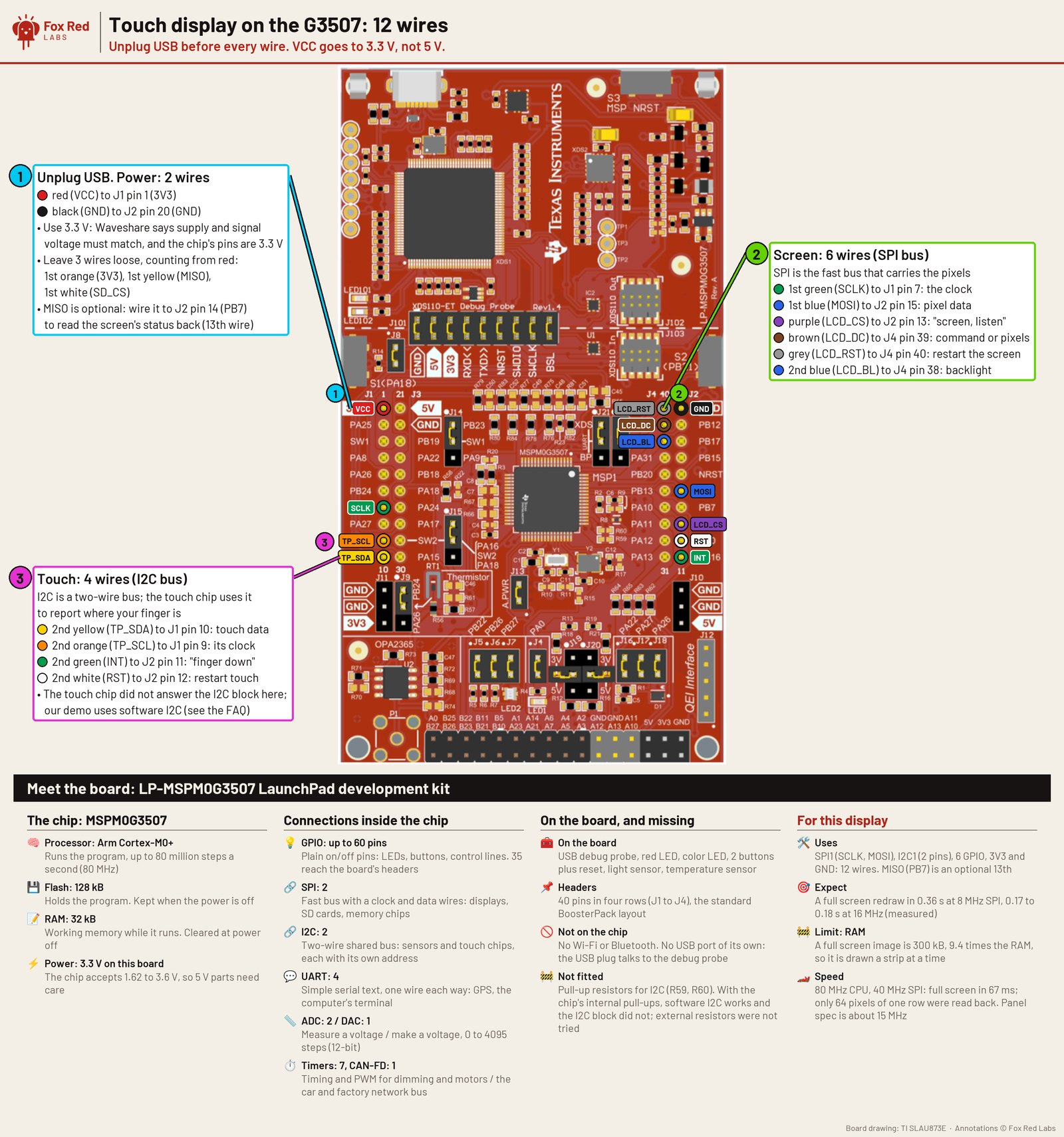
mspm0g3507/display-test/gen80/ti_msp_dl_config.h). Signal and supply are both 3.3 V: the module's level translator takes the LaunchPad kit's 3V3, and nothing is driven at 5 V. No jumper on the LaunchPad moves. Full size.Pin table
| Display pin | LaunchPad pin | What it is | Needed |
|---|---|---|---|
| VCC pin (not the 3V3 pin) | J1 pin 1 (3V3) | power, 3.3 V only | required |
| GND | J2 pin 20 (GND) | ground | required |
| SCLK | J1 pin 7 (PB9) | screen clock, SPI1 | required |
| MOSI | J2 pin 15 (PB8) | screen data in, SPI1 | required |
| LCD_CS | J2 pin 13 (PB6) | screen chip select | required |
| LCD_DC | J4 pin 39 (PB1) | command or data | required |
| LCD_RST | J4 pin 40 (PB4) | screen reset | required |
| LCD_BL | J4 pin 38 (PA28) | backlight on | required |
| TP_SDA | J1 pin 10 (PB3) | touch data, software I2C | required |
| TP_SCL | J1 pin 9 (PB2) | touch clock, software I2C | required |
| TP_INT | J2 pin 11 (PB16) | touch interrupt. The program reads it once at start for a diagnostic value and finds touches by polling the touch chip, so the demo does not need it. Wired in the tested setup. | optional |
| TP_RST | J2 pin 12 (PB0) | touch reset | required |
| MISO | J2 pin 14 (PB7) | screen read-back; only to diagnose a dark screen | optional |
| 3V3 pin and SD_CS | not connected | the module's own 3V3 pin, which stays empty, and its SD card select | leave off |
Set up your computer once: 1 step. Done already? Start at step 2.
Install the tools once, all free.TERMINAL
CCStudio 21.0.1 comes from TI's CCStudio download page (1.9 GB download, 8.1 GB installed, free myTI login); it brings TI Arm Clang 5.1.1. The MSPM0 SDK 2.11.00.07 comes from TI's MSPM0 SDK download page (0.4 GB download, 2.2 GB installed). xPack OpenOCD 0.12.0 comes from its GitHub release page (2 MB; the file
xpack-openocd-0.12.0-7-darwin-x64.tar.gzon an Intel Mac,xpack-openocd-0.12.0-7-darwin-arm64.tar.gzon Apple Silicon); get the macOS x64 archive and unpack it in your home folder. The OpenOCD connection file is in this repository, so nothing else is needed. Checked on an Intel Mac; on Apple Silicon CCStudio runs under Rosetta 2 by TI's own notes. Then clone this repository into<repository folder>. To fetch only the board folder, use the sparse-checkout line in its README. The model and upstream code are already in the tree underthird-party/bitnetmcu: GPL-3.0, commit 0715bfc, unchanged.You should see:
/Applications/ti/ccs2101/ccs/tools/compiler/ti-cgt-armllvm_5.1.1.LTS/bin/tiarmclang --versionprints 5.1.1, andls ports/bitnetmcu/touchshowsdigit_touch.c,build.sh,flash.sh,lcd_touch.h,prepare.handfont5x7.h.
With the LaunchPad unplugged, run the wires in the table above from the display to the header, power from the 3V3 pin only.BENCH
Leave the display's own 3V3 and SD_CS pins empty. The 13th wire, MISO, is only for diagnosing a dark screen.
You should see: Every wire sits on the header row the picture shows; nothing is plugged into the display's 3V3 or SD_CS.
Tell the build where your SDK and compiler are, check them, and build.TERMINAL
The two paths below are the installer defaults on this Mac; change them to where yours are. Keep the quotes: they let a path with spaces work. The build uses the tracked SysConfig output for an 80 MHz CPU and 20 MHz SPI.
Replace <repository folder> before you run this.
# replace <repository folder> with the folder you cloned this repository into export SDK="/Applications/ti/mspm0_sdk_2_11_00_07" export CC="/Applications/ti/ccs2101/ccs/tools/compiler/ti-cgt-armllvm_5.1.1.LTS" cd <repository folder>/ports/bitnetmcu/touch ./build.sh --check ./build.shYou should see:
check OK: every tool and setting this script needs was found, then two lines, FLASH and SRAM, thenbuilt .../out/digit_touch.out. On 2026-10-10 the image was 42.3 kB of flash and 5.0 kB of RAM. The linker map says 42.3 kB and 5 kB, and 4 kB of that RAM is the stack setting.Plug the LaunchPad in with a micro-USB data cable and list its serial ports.BENCH
Your probe id is the text after
usbmodemwithout the last digit:usbmodemAB1234561andusbmodemAB1234564are the two ports of probeAB123456. Flashing needs this id and will not guess it, so it can never flash a board that is not yours.ls /dev/cu.usbmodem*You should see: Two
cu.usbmodemlines per board, with the same text and last digits 1 and 4. The backlight may come on but the screen stays dark until step 5.Flash and start it.TERMINAL
Set
OCDto the folder you unpacked OpenOCD into, the one that holdsbin/openocd, andPROBEto your id from step 4;<probe serial>stands for your id, so replace it, brackets included. The check runs first and never opens the probe. To find yours, run/Applications/ti/ccs2101/ccs/ccs_base/common/uscif/xds110/xdsdfu -eif you have CCStudio (it printsSerial Num:), elsesystem_profiler SPUSBDataType | grep -A3 XDS110.Replace <probe serial> and <repository folder> before you run this.
export OCD="$HOME/xpack-openocd-0.12.0-7" export PROBE=<probe serial> cd <repository folder>/ports/bitnetmcu/touch ./flash.sh --check ./flash.shYou should see:
check OK, thenVerified OKandrunning: the screen should say DRAW A DIGIT. The script retries up to three times, because on this board OpenOCD's verify fails on about every other load and passes on the next. Suspected cause: Tool or docs. The retry handles it.Look at the screen.BENCH
You should see: "DRAW A DIGIT", a black box and a red CLEAR button, in portrait.
Draw one digit, 0 to 9, inside the box with a finger, then lift the finger.BENCH
You should see: About half a second after you lift, the answer and the time it took appear under the box. The inference takes 33 or 34 ms at 80 MHz.
Touch the box again or tap CLEAR to try another digit.BENCH
You should see: The box clears and the next digit is read the same way. It reads one digit at a time: "10" came out as 6 and "12" as 4 in the video, because the model knows single digits only.
You need
- LP-MSPM0G3507 LaunchPad development kit Buy the board these steps use
- Micro-USB data cable power and programming
Plug a micro-USB data cable into the debugger end of the MSPM0 L1306. No driver to install.
In Chrome or Edge, open the browser bench and click Connect.
Click Flash. The page writes the demo to the board.
You should see: Draw a digit from 0 to 9 with your mouse or finger. The chip's answer and its time appear beside it.
Set up your computer once: 1 step. Done already? Start at step 2.
Install the tools once, all free.TERMINAL
CCStudio 21.0.1 comes from TI's CCStudio download page (1.9 GB download, 8.1 GB installed, free myTI login); it brings TI Arm Clang 5.1.1. The MSPM0 SDK 2.11.00.07 comes from TI's MSPM0 SDK download page (0.4 GB download, 2.2 GB installed). xPack OpenOCD 0.12.0 comes from its GitHub release page (2 MB; the file
xpack-openocd-0.12.0-7-darwin-x64.tar.gzon an Intel Mac,xpack-openocd-0.12.0-7-darwin-arm64.tar.gzon Apple Silicon); get the macOS x64 archive and unpack it in your home folder. The OpenOCD connection file is in this repository, so nothing else is needed. Checked on an Intel Mac; on Apple Silicon CCStudio runs under Rosetta 2 by TI's own notes. Then clone this repository into<repository folder>. To fetch only the board folder, use the sparse-checkout line in its README.You should see:
/Applications/ti/ccs2101/ccs/tools/compiler/ti-cgt-armllvm_5.1.1.LTS/bin/tiarmclang --versionprints 5.1.1, andls ports/bitnetmcu/mspm0showsbuild.sh,run.shandmain.c.
Build the 64-wide model for the LP-MSPM0G3507 at 80 MHz.TERMINAL
The two paths are the installer defaults on this Mac; change them to where yours are. Keep the quotes: they let a path with spaces work. The check runs first and builds nothing.
Replace <repository folder> before you run this.
# replace <repository folder> with the folder you cloned this repository into export SDK="/Applications/ti/mspm0_sdk_2_11_00_07" export CC="/Applications/ti/ccs2101/ccs/tools/compiler/ti-cgt-armllvm_5.1.1.LTS" cd <repository folder>/ports/bitnetmcu/mspm0 ./build.sh --check g3507 80 ./build.sh g3507 cnn_64 O3 80You should see:
check OK, then the FLASH and SRAM lines of the linker map and a newbuild-g3507-cnn_64-O3-80folder. The lines read 23.0 kB of flash and 3.3 kB of RAM.Plug the LaunchPad in with a micro-USB data cable and list its serial ports.BENCH
Your probe id is the text after
usbmodemwithout the last digit:usbmodemAB1234561andusbmodemAB1234564are the two ports of probeAB123456. Flashing needs this id and will not guess it, so it can never flash a board that is not yours. No wiring is needed: the test digits are in the image.ls /dev/cu.usbmodem*You should see: Two
cu.usbmodemlines per board, with the same text and last digits 1 and 4.Run it on the LP-MSPM0G3507.TERMINAL
Set
OCDto the folder you unpacked OpenOCD into, the one that holdsbin/openocd, andPROBEto your id from step 3;<probe serial>stands for your id, so replace it, brackets included. The script flashes, fills RAM with a pattern, lets the board classify the ten digits for 20 seconds, then reads the answers, cycles and stack depth back over the debugger. To find yours, run/Applications/ti/ccs2101/ccs/ccs_base/common/uscif/xds110/xdsdfu -eif you have CCStudio (it printsSerial Num:), elsesystem_profiler SPUSBDataType | grep -A3 XDS110.Replace <probe serial> and <repository folder> before you run this.
export CC="/Applications/ti/ccs2101/ccs/tools/compiler/ti-cgt-armllvm_5.1.1.LTS" # run.sh finds its symbol tool, tiarmnm, inside this folder export OCD="$HOME/xpack-openocd-0.12.0-7" export PROBE=<probe serial> cd <repository folder>/ports/bitnetmcu/mspm0 ./run.sh --check build-g3507-cnn_64-O3-80 ./run.sh build-g3507-cnn_64-O3-80You should see:
check OK,magic 0xb17e0001 (done), clock 80000000 Hz, right 10 of 10,answers 3209069277,cycles 2748503 to 2754797 (mean 2,750,868; 34.39 ms)andstack: 3072 bytes reserved, deepest use 2288 bytes.Only with an LP-MSPM0L1306: build the same model for it at 32 MHz.TERMINAL
STACK=3600reserves 3.5 kB of the board's 4 kB of RAM for the stack, as the saved result did. The model's deepest use is 2.2 kB. The default 3,072 also links, so the number only sets the headroom shown in step 6.Replace <repository folder> before you run this.
# replace <repository folder> with the folder you cloned this repository into export SDK="/Applications/ti/mspm0_sdk_2_11_00_07" export CC="/Applications/ti/ccs2101/ccs/tools/compiler/ti-cgt-armllvm_5.1.1.LTS" cd <repository folder>/ports/bitnetmcu/mspm0 ./build.sh --check l1306 32 STACK=3600 ./build.sh l1306 cnn_64 O3 32You should see:
check OK, then the FLASH and SRAM lines and a newbuild-l1306-cnn_64-O3-32folder. The lines read 21.4 kB of flash and 3.6 kB of the board's 4 kB of RAM, which leaves 396 bytes.Run it on the LP-MSPM0L1306.TERMINAL
Use the id of this board, read as in step 3;
<probe serial>stands for your id, so replace it, brackets included. Before OpenOCD starts the script asks TI'sxdsdfutool, which is inside CCStudio, whether that probe is plugged in; setXDSDFUto its path if yours is elsewhere. To find yours, run/Applications/ti/ccs2101/ccs/ccs_base/common/uscif/xds110/xdsdfu -eif you have CCStudio (it printsSerial Num:), elsesystem_profiler SPUSBDataType | grep -A3 XDS110.Replace <probe serial> and <repository folder> before you run this.
export CC="/Applications/ti/ccs2101/ccs/tools/compiler/ti-cgt-armllvm_5.1.1.LTS" # run.sh finds its symbol tool, tiarmnm, inside this folder export OCD="$HOME/xpack-openocd-0.12.0-7" export PROBE=<probe serial> cd <repository folder>/ports/bitnetmcu/mspm0 ./run.sh --check build-l1306-cnn_64-O3-32 ./run.sh build-l1306-cnn_64-O3-32You should see:
check OK,magic 0xb17e0001 (done), clock 32000000 Hz, right 10 of 10,answers 3209069277,cycles 2646151 to 2653623 (mean 2,649,196; 82.79 ms)andstack: 3600 bytes reserved, deepest use 2288 bytes.
Or hand it to a coding assistant
Paste this in a terminal. It hands off to an AI assistant.
git clone --depth 1 --filter=blob:none https://github.com/Fox-Red-Labs/fox-red-labs.git && cd fox-red-labs
./start.sh mspm0g3507 handwritten-digits --assistant claudegit clone --depth 1 --filter=blob:none https://github.com/Fox-Red-Labs/fox-red-labs.git && cd fox-red-labs
py start.py mspm0g3507 handwritten-digits --assistant claudeIt runs the steps above and reports what it saw.
Not Claude Code? Copy this prompt instead.
Or hand it to a coding assistant
Paste this in a terminal. It hands off to an AI assistant, which says when to plug in each of the five boards.
git clone --depth 1 --filter=blob:none https://github.com/Fox-Red-Labs/fox-red-labs.git && cd fox-red-labs
./start.sh mspm0g3507 handwritten-digits --assistant claudegit clone --depth 1 --filter=blob:none https://github.com/Fox-Red-Labs/fox-red-labs.git && cd fox-red-labs
py start.py mspm0g3507 handwritten-digits --assistant claudeIt runs the steps above and reports what it saw.
Not Claude Code? Copy this prompt instead.
If something goes wrong
third-party/bitnetmcu is empty | The clone did not bring the third-party folder; it is part of this repository and is not a submodule, so re-clone. |
| Your tools live somewhere else | Step 4 and step 6 show how to point the scripts at them. |
| You are not sure a wire is on the right pin | Count from the header's pin 1 and check it against the table before plugging in. Pin 1 is the corner nearest the USB connector, J1. |
The check prints Not ready it names each missing item and how to fix it; set SDK or CC to the folder it says and run it again. Downloads: MSPM0 SDK | CCStudio. |
| Nothing appears | The cable is charge-only; swap it for a data cable. |
More troubleshooting
| Several boards are plugged in | Unplug the others, or run system_profiler SPUSBDataType | grep -A6 XDS110 and read the Serial Number line of the board you mean. |
PROBE: not set appears | Step 4 shows how to read it. |
All three tries fail with Verify Failed | See the OpenOCD CRC mismatch entry; if it says no device, replug and check the probe id against ls /dev/cu.usbmodem*. |
| The screen is dark or shows static with every wire right | See the screen stays dark entry: the chip-select gap or a wire is the usual cause. |
| The backlight is off | LCD_BL on J4 pin 38 is the first wire to check. |
| Nothing follows the finger | Touch is not answering: the touch chip at address 0x38 entry has the two checks: the software I2C pins and TP_RST. |
| A digit is read wrong | Draw it larger and centered; the drawing is scaled and centered like the MNIST training digits before it is read. |
Every fix for this board: the FAQ.
| Your copies live elsewhere | Steps 2 to 6 set SDK, CC and OCD to your paths; each script prints what it could not find. |
The check prints Not ready it names each missing item and how to fix it. Downloads: MSPM0 SDK | CCStudio. Clock 80 exists for the G3507 only; the L1306 uses 32. |
| Nothing appears | The cable is charge-only; swap it for a data cable. |
| Several boards are plugged in | Unplug the others, or run system_profiler SPUSBDataType | grep -A6 XDS110 and read the Serial Number line of the board you mean. |
right is under 10 or the magic says NOT DONE | The image did not run to the end: reflash, and check you built clock 80 for this board. run.sh already retries OpenOCD's verify three times; for the known verify failure see the OpenOCD CRC mismatch entry. |
More troubleshooting
It prints PROBE: not set | Step 3 shows how to read it. |
| The link fails with a stack or RAM error | The model is too big for 4 kB: use cnn_64, or a smaller model (cnn_16small, 12k, 1k). STACK is the stack size in bytes. |
It prints Probe ... missing | That id is not on the USB bus: replug, and compare with ls /dev/cu.usbmodem*. |
right is under 10 or the magic says NOT DONE | Reflash and check you built clock 32 with STACK=3600. Otherwise the stack line reads 3 kB reserved. |
Every fix for this board: the FAQ.
What to build next
Every build. The code for all of them is in the GitHub repository.
Evidence and limitsOn the MSPM0 G3507 the chip reads a finger-drawn digit in 34 ms at 80 MHz; the demo waits half a second after the finger lifts before it looks. The ten stored test digits pass on the G3507, L1306, CC1354P10 and F2800137, and the 1k model on the C1104. Ran on 5 boards. Results, sources, timing and limits.
Draw on a touch screen
Expected result: A digit drawn with a finger is answered on screen about half a second after you lift the finger. The inference time, 34 ms at 80 MHz, appears beside it. The demo waits half a second on purpose before it reads the drawing. The 560 ms from lift to answer is computed from the wait, the 25 ms of preparation and the inference. It was not measured end to end.
What this shows
- The 64-wide BitNetMCU model runs on the MSPM0 G3507 and reads the ten digits that ship with it, 10 of 10, through the same drawing path a finger uses. The self-test does this at power-up. The author reports 99.55% on MNIST for this model.
- Finger-drawn digits were read on camera: counted from the video, seven of the nine drawings were single digits and all seven were read right. No larger count exists.
- One inference takes 2.71M cycles on the demo's path, 34 ms at 80 MHz; turning the drawing into the model's 16 x 16 input takes another 25 ms.
What this does not establish, and limits
What this does not establish
- How often it reads a stranger's handwriting right. The 10 stored digits are a port check and not an accuracy measurement. The only count of finger drawings is the seven in the video.
- The 99.55% is the author's figure on the MNIST test set. It is not measured here, and it is not on finger input.
- Pen-to-answer time. The demo waits half a second after the finger lifts, then spends 25 ms preparing and 34 ms inferring, so the answer appears about 560 ms after the lift. That figure is computed and was not measured end to end. The 34 ms is the model alone.
- Letters or two-digit numbers: the model was trained on single digits.
- That 20 MHz SPI is safe everywhere. The data sheet rates SPI1's standard-drive pins to 16 Mbit/s. The panel's allows about 15 MHz. The display test read back only 64 pixels of one row at 20 and 40 MHz. It worked here on 10 to 20 cm wires.
Limits to keep in mind
- Touch runs over software I2C on PB3 and PB2 because the chip's I2C block did not get an answer from the touch controller through the module. The translator is suspected and was not checked.
- Chip select needs a 10 microsecond gap between commands or the screen drops the second one; the driver has it, a rewritten driver must keep it.
- SPI runs at 20 MHz, over the 16 Mbit/s the data sheet gives these pins and the 15 MHz the panel allows. If you see wrong colors or noise, change the divider in
digit_touch.c(DL_SPI_setBitRateSerialClockDivider(LCD_SPI_INST, 1)) from 1 to 2 for 13.3 MHz.
Sources
Why this board
The MSPM0 G3507 has 32 kB of RAM and 128 kB of flash against this build's 5.0 kB and 42.3 kB. That leaves room for a bigger model or a user interface. The MSPM0 L1306 runs the stored model, but its 4 kB of RAM leaves no room for this screen demo as built.
Versions, sizes and timing
| Model | BitNetMCU 64-wide CNN, 11.0 kB of weights, commit 0715bfc, unchanged | README notes |
|---|---|---|
| Inference | 2.71M cycles on the demo's drawing path (34 ms at 80 MHz); the separate benchmark image measures 2,750,868 at 80 MHz with two flash wait states | README notes |
| Preprocessing | 1.97M cycles, 25 ms at 80 MHz, in software floating point: the digit's larger side scaled to 20 of 28 pixels, center of mass centered, shrunk to 16 x 16, normalized like the training data | the source |
| Clock and SPI | 80 MHz CPU from the SysPLL (display80.syscfg), SPI1 at 20 MHz, 16-bit frames | README notes |
| Compiler and SDK | TI Arm Clang 5.1.1.LTS at -O3, MSPM0 SDK 2.11.00.07, SysConfig 1.26.3, xPack OpenOCD 0.12.0 | MSPM0 bitnetmcu notes |
| Screen driver | ST7796S over SPI and FT6336U over bit-banged I2C, copied from the display test with the I2C delay scaled to the clock | README notes |
| Image | 43,304 bytes of flash (42.3 kB) and 5,128 bytes of RAM (5.0 kB, of which 4,096 is the stack setting), from the linker map of the 2026-10-10 build |
Evidence
- Ran on the MSPM0 G3507 on 2026-10-06 and 2026-10-07. The self-test read 10 of 10 stored digits through the drawing path, and finger-drawn digits were read on camera. Counted from the video afterwards, 7 of the 9 drawings were single digits, and all 7 were read right. MSPM0 bitnetmcu notes
- The video is the proof a reader can see. bitnetmcu-touch-demo.mp4
Other boards
- F2800137Could work not assessed
- CC1354P10Could work could work
- MSPM0L1306, MSPM0C1104could work
- CC2340R5not assessed
- MSPM0G3519should work
What the status words mean
Works ran here and did what it shouldCould work some of it ran; real porting effort is left; hover for whatNot for this chip the chip or its vendor software cannot; hover for why
Run stored test digits without a screen
Expected result: right 10 of 10 and the answers 3209069277, the same ten the Mac gives from host/host_main.c.
What this shows
- Every board that ran it gave the same ten answers as the Mac for the model it ran, and the board table says which model. So the port is correct.
- Cycle counts per digit are comparable with the author's CH32V002 figure: fewer at 32 MHz on the MSPM0 boards, 0.5% more at 80 MHz with two flash wait states.
What this does not establish, and limits
What this does not establish
- Nothing about handwriting: no touch input, no finger. Passing ten stored vectors is a functional check of the port and is no accuracy estimate.
- A passing stored run on a board does not mean the touch build works there; that needs the screen driver on that board.
Limits to keep in mind
- On the MSPM0 L1306 only the 64-wide model was run, with a 3.5 kB stack leaving 396 bytes of RAM; the SRAM-loop variant does not fit.
- The author's cycle counts were not rerun on his chip; the comparison is chip plus compiler.
Sources
Why this board
Any of the five boards that ran it is enough for this check. These steps and the build script use the MSPM0 G3507: 32 kB of RAM against the model's 2.2 kB of stack. The MSPM0 L1306 at the same price shows the model in 4 kB of RAM.
Versions, sizes and timing
| Cycles per digit, 64-wide model | G3507 2,640,383 at 32 MHz and 2,750,868 at 80 MHz; L1306 2,649,196 at 32 MHz; CC1354P10 about 1.13M at 48 MHz; F2800137 2,551,750 from RAM and 2,897,585 from flash at 120 MHz; author's CH32V002 2,736,250 | README notes |
|---|---|---|
| Stack | 2.2 kB deepest use on the MSPM0 boards (RAM painted before the run) | |
| Models | 64-wide CNN 11.0 kB (99.55%), 16-wide 3.2 kB (98.92%), 12k fully connected 12.3 kB (99.02%), 1k 1.1 kB (94.22%); accuracies are the author's on MNIST | README notes |
| C28x patches | 1L << shift in ReLUNorm, signed test-data bytes, a 2-word alignment on one shared buffer; the arithmetic is unchanged |
Evidence
- MSPM0 G3507: all four models 10 of 10 at 32 MHz; the 64-wide model also 10 of 10 at 80 MHz (the other three were not run at 80 MHz).
- MSPM0 L1306: the 64-wide model 10 of 10 in 4 kB of RAM, 2.65M cycles.
- CC1354P10-1: the 64-wide model, 0 failed, about 1.13M cycles per digit at 48 MHz.
- LAUNCHXL-F2800137: 10 of 10 from RAM in 2.55M cycles after three patches for the 16-bit char.
- MSPM0 C1104: the 1k model 10 of 10 in 804 B of RAM; the 16-channel model overruns its stack and the 12k model does not link. MSPM0C1104 1kb ram notes
Other boards
- CC2340R5, MSPM0G3519should work
What the status words mean
Works ran here and did what it shouldCould work some of it ran; real porting effort is left; hover for whatNot for this chip the chip or its vendor software cannot; hover for why
Result grid
Details
At 32 MHz it takes fewer cycles than the WCH chip it was written for, and at 80 MHz 0.5% more, at 34 ms per inference. A touchscreen demo reads finger-drawn digitsDetails
forDetails
the C28x's 16-bit charWorks ran here and did what it shouldShould work it builds; only naming, packaging or build glue is in the way; hover for whichCould work some of it ran; real porting effort is left; hover for whatNot for this chip the chip or its vendor software cannot; hover for why
Experiments (3)
| Status | What was tried | Result |
|---|---|---|
| Works | Can the TI LP-MSPM0G3507 LaunchPad development kit run BitNetMCU's handwriting recognizer as well as the WCH chip it was written for? MSPM0 G3507, 2026-10-07 | All four BitNetMCU handwriting models read 10 of 10 test digits on the MSPM0 G3507; at 32 MHz each took 3.5 to 19% fewer cycles than the author's CH32V002 figures, at 80 MHz (two wait states) the 99.55% model took... |
| Works | Can a TI LP-MSPM0C1104 LaunchPad development kit, with 1 kB of RAM, run a neural net that reads handwritten digits? MSPM0 C1104, 2026-10-08 | BitNetMCU's 1k handwriting model reads all 10 test digits right on the MSPM0 C1104 in 804 B of RAM; the 16-channel CNN links but overruns the stack and never finishes. |
| Works | Can the NXP FRDM-MCXA153 run BitNetMCU's handwriting recognizer, and how many cycles does it need? FRDM-MCXA153, 2026-10-11 | All four BitNetMCU models read 10 of 10 digits right on the FRDM-MCXA153 with the inference code unchanged; the 64-wide CNN takes 1.30M cycles, about half the MSPM0 G3507's count at 32 MHz. |
Source files
- Experiment write-up (MSPM0 G3507 and MSPM0 L1306): what was tried and where it stopped
Code brought from elsewhere
This project uses code that was written for other chips or tools. Each links to how to get it running.
- BitNetMCU handwriting AI on MSPM0 Works BitNetMCU handwriting models read all 10 test digits right on the MSPM0 G3507 and MSPM0 L1306, the same answers as on a Mac.
- BitNetMCU in 1 kB of RAM on the LP-MSPM0C1104 Works The 1k handwriting model reads all 10 test digits right in 804 B of RAM on the MSPM0 C1104.
- BitNetMCU on a C2000 control chip (LAUNCHXL-F2800137) Works BitNetMCU's 64-wide CNN reads all 10 test digits right on the LAUNCHXL-F2800137.
Get the code and tell us how it wentThe clone command, the board folder with its AGENTS.md, reports from others, and the three report forms.
Get the code
Clone the repository and open the board's folder below. AGENTS.md is a plain text file of notes for AI coding assistants, and llms.txt at the root indexes the site for one.
git clone https://github.com/Fox-Red-Labs/fox-red-labs.git- LP-MSPM0G3507: folder
mspm0g3507/.- README: the board's lab notebook (what was run, in order)
- Notes for an AI coding assistant working in this repository: notes for an AI assistant; copy it into your own project if you use one
- FAQ: errors and fixes
The other 4 board folders
- LP-MSPM0L1306: folder
mspm0l1306/.- README: the board's lab notebook (what was run, in order)
- Notes for an AI coding assistant working in this repository: notes for an AI assistant; copy it into your own project if you use one
- FAQ: errors and fixes
- LAUNCHXL-F2800137: folder
c2000-launchpad/.- README: the board's lab notebook (what was run, in order)
- Notes for an AI coding assistant working in this repository: notes for an AI assistant; copy it into your own project if you use one
- FAQ: errors and fixes
- LP-CC1354P10-1: folder
cc1354p10/.- README: the board's lab notebook (what was run, in order)
- Notes for an AI coding assistant working in this repository: notes for an AI assistant; copy it into your own project if you use one
- FAQ: errors and fixes
- LP-MSPM0C1104: folder
mspm0c1104/.- README: the board's lab notebook (what was run, in order)
- Notes for an AI coding assistant working in this repository: notes for an AI assistant; copy it into your own project if you use one
- FAQ: errors and fixes
- LP-MSPM0L1306: folder
Code is BSD-3-Clause, writing is CC BY 4.0; third-party folders keep their own licenses.
Built it? Tell us
Built this, or got stuck? Report it on GitHub with a few short answers. Your report shows here in your words, marked as yours. A failure that repeats on the bench gets its fix here.