Fox Red Labs / Builds / Motor control, power and sensing
Spin a brushless motor: six-step, FOC and sensorless FOC
An AM13E230 and a plug-on driver board turn a Hall-sensor motor; drive it from the serial port, the browser console or a phone.
HardWiring needed1 evening for six-step
Parts and steps
Which version
You need
- LP-AM13E230 LaunchPad development kit the board
- DRV8376EVM three-phase motor driver evaluation module the motor driver
- Anaheim Automation BLY171S-24V-4000 brushless motor Buy the motor
- 12 V DC power supply, 0.5 A or more motor power, to the VBAT and PGND screw terminals
- Small screwdriver for the screw terminals: 3 motor phase wires, 5 Hall wires and the 2 supply wires
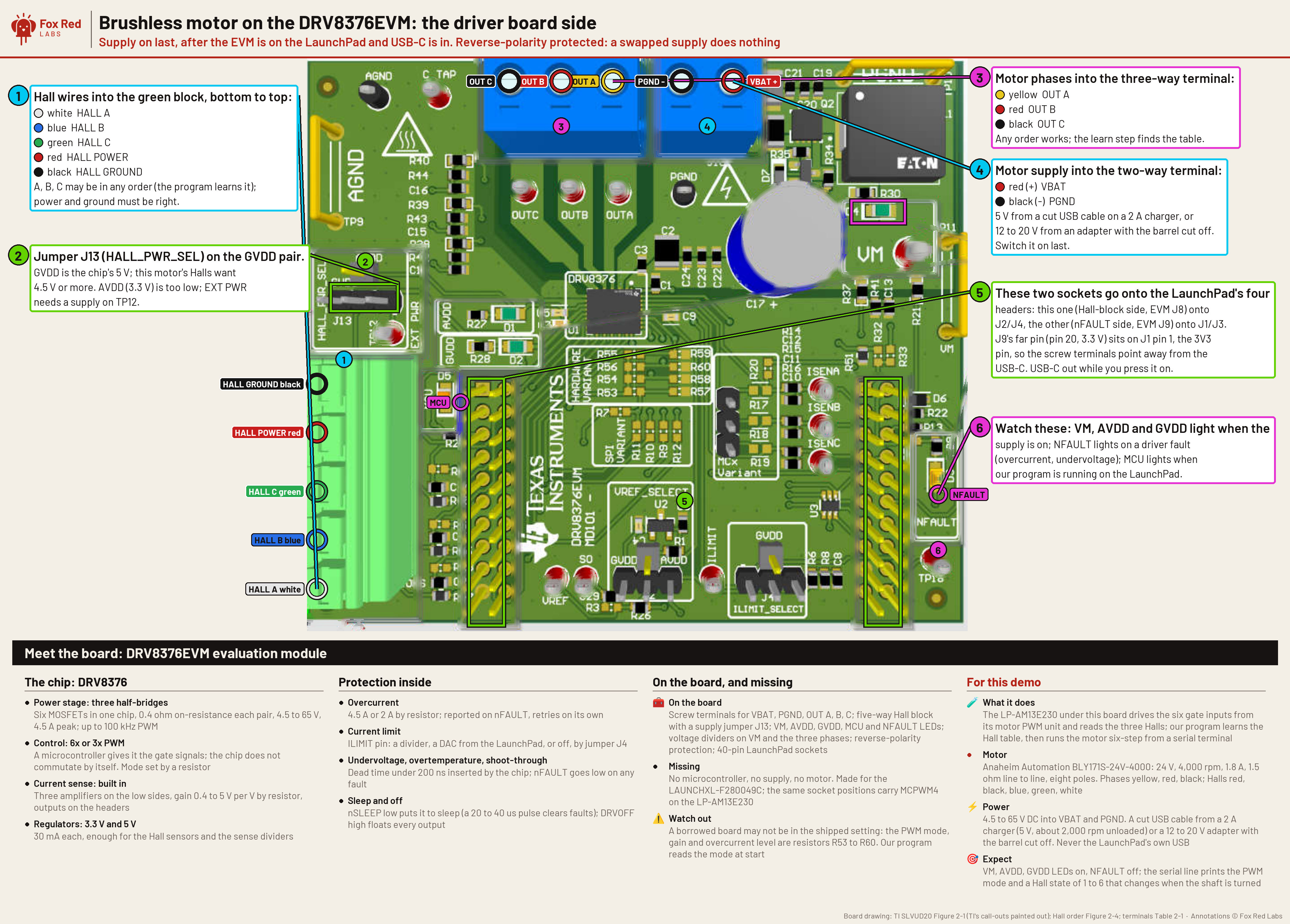
Pin table
| EVM pin | LaunchPad pin | What it is | Needed |
|---|---|---|---|
| EVM INHA, INLA | J4 pins 40, 39 (PB3, PA7) | gate drive, phase A: MCPWM4 1A, 1B | required |
| EVM INHB, INLB | J4 pins 38, 37 (PB1, PA2) | gate drive, phase B: MCPWM4 2A, 2B | required |
| EVM INHC, INLC | J4 pins 36, 35 (PB2, PA25) | gate drive, phase C: MCPWM4 3A, 3B | required |
| EVM HALL A, B, C | J4 pins 34, 33, 32 (PB7, PB6, PA12) | Hall inputs; the EVM has 10 k pull-ups to 3.3 V | required |
| EVM nSLEEP | J1 pin 9 (PA23) | high wakes the driver | required |
| EVM nFAULT | J1 pin 8 (PB4) | low means a driver fault | required |
| EVM DRVOFF | J2 pin 13 (PB18) | driver output enable | required |
| EVM VSENVM | J3 pin 23 (PA16) | bus voltage through the EVM's divider | required |
| EVM VSENA | J3 pin 26 (PA17) | phase A voltage | optional |
| LaunchPad S6 and S4 | both to BP | send PB6, PB7, PA11 and PA12 to the headers, not the CAN chip | required |
| EVM J13 | GVDD position (5 V) | powers the Hall sensors; the motor's Halls want 4.5 V or more | required |
With USB unplugged: set EVM jumper J13 to GVDD, wire the motor and Hall leads as in the table, set LaunchPad switches S6 and S4 to BP, and press the EVM onto J1 to J4 with its screw terminals pointing away from the USB-C connector.BENCH
You should see: The EVM sits flat on all four headers. Nothing is lit.
Build and flash the six-step program: cd am13e230/bldc-drv8376 && ./build.sh --flashTERMINAL
You should see: About 3 s to build and 5 s to flash over the LaunchPad kit's own probe; 32 kB of flash.
Plug in USB-C, then switch the motor supply on.BENCH
Open the LaunchPad kit's serial port at 115200 baud and type
v.You should see: The EVM's VM, AVDD and GVDD lights are on and NFAULT is off.
vshows bus volts near your supply and a Hall state from 1 to 6. The current image boots with the driver off; Check the supply voltage and the driver wiring before the first start.Learn the Hall table once per power-up: type l.TERMINAL
It takes about 25 s with no hands.
You should see: The shaft clicks round six steps and a table prints with six different Hall states.
Type 2 then g.TERMINAL
2gYou should see: The motor turns. A line a second shows duty, direction, Hall state, rpm, bus volts and fault. At 20 percent duty it settles near 920 rpm.
Type s, then r, then g for the other direction. b brakes. 0 then s ends.TERMINAL
You should see: Reverse runs 4 to 10 percent slower than forward at the same duty.
You need
- LP-AM13E230 LaunchPad development kit the board
- DRV8376EVM three-phase motor driver evaluation module the motor driver
- Anaheim Automation BLY171S-24V-4000 brushless motor Buy the motor
- 12 V DC power supply, 0.5 A or more motor power, to the VBAT and PGND screw terminals
- Small screwdriver for the screw terminals: 3 motor phase wires, 5 Hall wires and the 2 supply wires
Pin table
| EVM pin | LaunchPad pin | What it is | Needed |
|---|---|---|---|
| EVM INHA, INLA | J4 pins 40, 39 (PB3, PA7) | gate drive, phase A: MCPWM4 1A, 1B | required |
| EVM INHB, INLB | J4 pins 38, 37 (PB1, PA2) | gate drive, phase B: MCPWM4 2A, 2B | required |
| EVM INHC, INLC | J4 pins 36, 35 (PB2, PA25) | gate drive, phase C: MCPWM4 3A, 3B | required |
| EVM HALL A, B, C | J4 pins 34, 33, 32 (PB7, PB6, PA12) | Hall inputs; the EVM has 10 k pull-ups to 3.3 V | required |
| EVM nSLEEP | J1 pin 9 (PA23) | high wakes the driver | required |
| EVM nFAULT | J1 pin 8 (PB4) | low means a driver fault | required |
| EVM DRVOFF | J2 pin 13 (PB18) | driver output enable | required |
| EVM VSENVM | J3 pin 23 (PA16) | bus voltage through the EVM's divider | required |
| EVM VSENA | J3 pin 26 (PA17) | phase A voltage | optional |
| LaunchPad S6 and S4 | both to BP | send PB6, PB7, PA11 and PA12 to the headers, not the CAN chip | required |
| EVM J13 | GVDD position (5 V) | powers the Hall sensors; the motor's Halls want 4.5 V or more | required |
Wire it as in the six-step version, with the 12 V supply, and make sure J2 (the current-sense reference) is fitted.BENCH
You should see: Same layout. With power on and the motor stopped, the phase-current sense outputs rest near half scale.
Build the normal image, the one with the bench guard: cd am13e230/foc-drv8376 && OUT=$HOME/frl-build FRL_COMMISSIONING=0 ./build.shTERMINAL
You should see: foc.out and foc.map in $HOME/frl-build/foc-drv8376/ (OUT sets the parent folder). The script builds and never flashes.
Flash it over the LaunchPad kit's probe: python3 am13e230/tools/run_image.py $HOME/frl-build/foc-drv8376/foc.out 3TERMINAL
You should see: The flash verifies and the program starts. The script flashes the bench's own probe by default; for yours pass
--serial <probe serial>and add a matching AM13E23019_<probe serial>.ccxml beside the existing one in am13e230/.Read the board: python3 tools/motorlink/link.py pollTERMINAL
You should see: State reads stop idle, bus volts near your supply, phase currents under 3 mA.
Learn the Hall angle once, under the probe lock: python3 tools/frl/lock.py exec --serial <probe serial> --op motor-campaign -- python3 tools/motorlink/campaign.py cal To find yours, run /Applications/ti/ccs2101/ccs/ccs_base/common/uscif/xds110/xdsdfu -e if you have CCStudio (it prints Serial Num:), else system_profiler SPUSBDataType | grep -A3 XDS110.TERMINAL
You should see: State reports calibration, then idle, with the Hall table marked valid. It took 171 s on the bench; the guard allows up to 700 s.
Set the guard's bus window for the supply, then run at 10 Hz electrical: campaign.py supply adapter12, then campaign.py fwd 10 OUTDIR TAG, each under the same lock.py exec line as step 5 (supply takes adapter12 or pack20).TERMINAL
You should see: The motor aligns, opens loop, reaches closed loop at about 9 s and stops at the 12 s run cap. Speed in rpm is Hz x 15 for four pole pairs. Raw streams land in OUTDIR.
Or drive it by hand: Connect to the board and watch the motor live in Chrome or Edge, click Connect, set a speed under 40 Hz and click Run.BROWSER
STOP is always on screen.
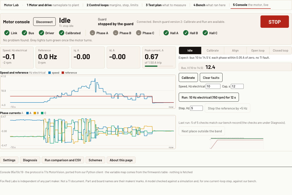
You should see: The state lights step Calibrate, Align, Open loop, Closed loop; speed, id, iq, peak current and bus volts update live.
Try the designed speed gains, under the lock: python3 tools/motorlink/campaign.py gstep 0.0131 0.0157 200 OUTDIR TAG, then python3 tools/motorlink/speedloop_analyse.py on the folder.TERMINAL
You should see: Settle at 10 Hz, step to 15 Hz at 14 s. Median rise about 50 ms against 91 ms on TI's defaults.
Drive it from a phone.PHONE
Phones have no Web Serial, so the computer that holds the board's USB port serves the same page with a stand-in serial port. Run the bridge under the probe lock with your own serial port and a private address of the computer; it prints one link with a random token. This is the home network, not Bluetooth. The remote's controls were checked against a simulated board; a run of the phone page on the real motor is not recorded.
Replace <probe serial> and <private address of this computer> before you run this.
python3 tools/frl/lock.py exec --serial <probe serial> --op phone-console -- node tools/motorlink/phone_console.mjs --port /dev/cu.usbmodem<probe serial>1 --host <private address of this computer>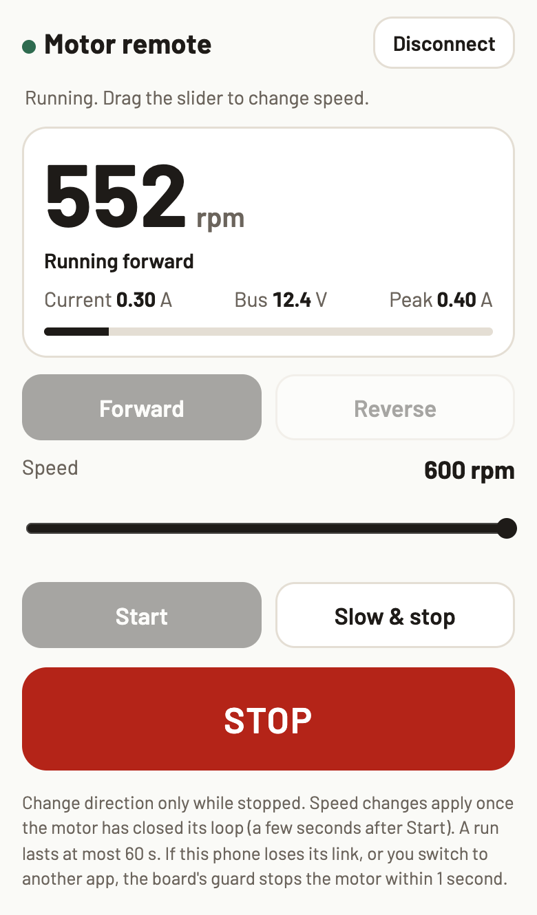
You should see: The page prints a link; opening it on the phone shows the Motor remote with Connect, Forward, Reverse, a speed slider, Start, Slow and stop, and a red STOP button. The board's guard stops the motor within 1 s if the phone goes quiet.
Optional: TI's own tool.BROWSER
TI publishes the MCU Motor Control GUI, a graphical tool for configuring and tuning motors, on its public tool page (download
MCU_Motor_Control_GUI.zip, release notes on the same page). That page lists C2000 boards and reference designs as supported and does not list the AM13E230. The AM13E2x SDK's Hall FOC example sends its variables over a UART at 9.2 Mbaud to MotorVision, the protocol this repository's console speaks. No recorded run connects TI's GUI to this board.You should see: Nothing to check here: this step only points to TI's tool.
You need
- LP-AM13E230 LaunchPad development kit the board
- DRV8376EVM three-phase motor driver evaluation module the motor driver
- Anaheim Automation BLY171S-24V-4000 brushless motor Buy the motor
- 12 V DC power supply, 0.5 A or more motor power, to the VBAT and PGND screw terminals
- Small screwdriver for the screw terminals: 3 motor phase wires, 5 Hall wires and the 2 supply wires
Pin table
| EVM pin | LaunchPad pin | What it is | Needed |
|---|---|---|---|
| EVM INHA, INLA | J4 pins 40, 39 (PB3, PA7) | gate drive, phase A: MCPWM4 1A, 1B | required |
| EVM INHB, INLB | J4 pins 38, 37 (PB1, PA2) | gate drive, phase B: MCPWM4 2A, 2B | required |
| EVM INHC, INLC | J4 pins 36, 35 (PB2, PA25) | gate drive, phase C: MCPWM4 3A, 3B | required |
| EVM HALL A, B, C | J4 pins 34, 33, 32 (PB7, PB6, PA12) | Hall inputs; the EVM has 10 k pull-ups to 3.3 V | required |
| EVM nSLEEP | J1 pin 9 (PA23) | high wakes the driver | required |
| EVM nFAULT | J1 pin 8 (PB4) | low means a driver fault | required |
| EVM DRVOFF | J2 pin 13 (PB18) | driver output enable | required |
| EVM VSENVM | J3 pin 23 (PA16) | bus voltage through the EVM's divider | required |
| EVM VSENA | J3 pin 26 (PA17) | phase A voltage | optional |
| LaunchPad S6 and S4 | both to BP | send PB6, PB7, PA11 and PA12 to the headers, not the CAN chip | required |
| EVM J13 | GVDD position (5 V) | powers the Hall sensors; the motor's Halls want 4.5 V or more | required |
Have the guarded FOC image flashed and the Hall table calibrated: steps 2, 3 and 5 of the FOC version.TERMINAL
The observer commands need guard version 6;
campaign.pyrefuses to run on another version.You should see:
link.py pollreads stop idle, with the Hall table valid.Find where the rotor really is: campaign.py sweep 2 40 OUTDIR TAG, under the same tools/frl/lock.py exec line as the FOC version's step 5.TERMINAL
It steps the FOC angle by -45 to +45 degrees at 40 Hz with the Halls driving.
You should see: Phase current falls from 0.129 A at 0 degrees to 0.089 A near +49 degrees, and a -45 degree step stalls the motor. The current minimum is the true rotor angle.
Shadow run: the Halls drive, FAST runs beside them: campaign.py obs 2 0 40 40 15 OUTDIR TAG (observer 2 = FAST, hand-over off, speed ceiling 40 Hz, reference 40 Hz, 15 s cap).TERMINAL
You should see: FAST reads about 50 degrees from the Hall angle and its speed is within 0.4 Hz of the Halls'.
Run with no Halls in the loop: campaign.py hallfree 2 0 40 20 OUTDIR TAG (observer FAST, no trim, 40 Hz reference, 20 s cap).TERMINAL
You should see: TI's align (5 s at 0.36 A) and open loop to 30 Hz, then FAST takes over at about 8 s. The speed holds at 40.0 Hz and phase current reads about 0.063 A. The Halls are only logged against it.
Or hand it to a coding assistant
Paste this in a terminal. It hands off to an AI assistant.
git clone --depth 1 --filter=blob:none https://github.com/Fox-Red-Labs/fox-red-labs.git && cd fox-red-labs
./start.sh am13e230 bldc-spin --assistant claudegit clone --depth 1 --filter=blob:none https://github.com/Fox-Red-Labs/fox-red-labs.git && cd fox-red-labs
py start.py am13e230 bldc-spin --assistant claudeIt runs the steps above and reports what it saw.
Not Claude Code? Copy this prompt instead.
Or hand it to a coding assistant
Paste this in a terminal. It hands off to an AI assistant.
git clone --depth 1 --filter=blob:none https://github.com/Fox-Red-Labs/fox-red-labs.git && cd fox-red-labs
./start.sh am13e230 bldc-spin --assistant claudegit clone --depth 1 --filter=blob:none https://github.com/Fox-Red-Labs/fox-red-labs.git && cd fox-red-labs
py start.py am13e230 bldc-spin --assistant claudeIt runs the steps above and reports what it saw.
Not Claude Code? Copy this prompt instead.
Or hand it to a coding assistant
Paste this in a terminal. It hands off to an AI assistant.
git clone --depth 1 --filter=blob:none https://github.com/Fox-Red-Labs/fox-red-labs.git && cd fox-red-labs
./start.sh am13e230 bldc-spin --assistant claudegit clone --depth 1 --filter=blob:none https://github.com/Fox-Red-Labs/fox-red-labs.git && cd fox-red-labs
py start.py am13e230 bldc-spin --assistant claudeIt runs the steps above and reports what it saw.
Not Claude Code? Copy this prompt instead.
If something goes wrong
| Every Hall line later reads state 7 | The J13 jumper is missing or the Hall ground lead is open. |
| The build cannot find its tools | Install the SDK, SysConfig and compiler versions in step 1. |
It says no bus voltage on VM | The supply is off or on the wrong terminals. |
It says learn failed | A Hall wire is loose (state 0 or 7), or the rotor did not move: raise the supply voltage. |
It says DRIVER FAULT | Lower the duty and check the supply can give the current, then type c to clear. |
More troubleshooting
| It runs rough or stalls at once | Type a to trim the commutation advance, then g again. |
Every fix for this board: the FAQ.
| The sense outputs read a few millivolts | J2 is missing. |
| At step 2 | Without FRL_COMMISSIONING=0 the script builds the commissioning console instead, which does not run TI's state machine. |
| At step 3 | If the flash does not return in 90 s the script stops it and tries once more; a probe held by CCStudio or another program is reported as busy. |
| The fault word reads 8192 (a gate driver fault) | The board is not running the guarded image; flash it again. |
| Calibration fails | TI's estimator fault is raised: check the five Hall wires and that the shaft can turn freely. |
More troubleshooting
The start is refused with bus out of range | The supply is outside the window you set. |
| Connect finds no board | It needs the normal image from step 3, not the commissioning build. |
| A run ends before the step | The guard's 20 s cap or a fault stopped it: read frlGuard.reason from link.py poll. |
| The phone cannot reach the link | Check that it is on the same private network as the computer. Details: tools/motorlink/BRIDGE.md. |
| You try it | Note what the GUI says about the board; the console in step 7 is the tested way to see the same variables. |
Every fix for this board: the FAQ.
The campaign stops with board is not on guard version 6 | Rebuild and flash the current am13e230/foc-drv8376. |
| At step 2 | A stall on the negative steps is expected and the guard stops it; clear faults with the console's Clear faults button before the next run. |
| FAST's speed is far from the Halls' below about 20 Hz | Run faster: both observers lock above about 20 Hz electrical here. |
| It faults in start-up | Check the Hall-free flag was applied: the campaign prints the config it read back before it starts. |
Every fix for this board: the FAQ.
What to build next
Every build. The code for all of them is in the GitHub repository.
Evidence and limitsSpins on all three: six-step to 3,632 rpm, Hall FOC held at a set speed, and sensorless FOC at 40 Hz on 0.063 A against 0.13 A on the Halls. Unloaded, 12.4 V. Ran on 1 board. Results, sources, timing and limits.
Six-step on the Hall sensors
Expected result: At 10 to 60 percent duty the motor runs from about 400 to about 3,630 rpm forward and 380 to 3,440 rpm in reverse, unloaded, on 12.4 V.
What this shows
- A plug-on driver board and about 350 lines of C turn a Hall-sensor motor, with the Hall table learned by the program in about 25 s.
- Unloaded, the motor started from standstill on every try at 10 and at 20 percent duty.
- Median speed at 20, 40 and 60 percent duty, forward: 924, 2,312 and 3,632 rpm; reverse: 891, 2,091 and 3,442.
What this does not establish, and limits
What this does not establish
- Torque or efficiency: nothing was loaded and phase current was not measured in this version.
- That the speeds are exact: they come from Hall edge timing, and a tachometer would settle whether they read high.
- That the speed sweep repeats: it was run once. The same motor later turned under the FOC image.
Limits to keep in mind
- Open loop in duty: speed follows the duty you type, with no speed loop in the base program.
- One motor, one driver board, 12.4 V from a small adapter, 60 percent duty cap, unloaded.
- The Hall sensors sit about 7 electrical degrees off their ideal spacing; the program learns the table rather than assuming it.
Sources
Versions, sizes and timing
| Speed sweep | 10 to 60 percent duty, 3 runs each, 20 kHz PWM, 6x PWM mode, Hall-timed rpm | README notes |
|---|---|---|
| Motor | Anaheim BLY171S-24V-4000: 24 V, 4,000 rpm, 1.8 A, 4 pole pairs, 2.45 V per 1,000 rpm (label) | README notes |
Evidence
- Duty sweep on 2026-10-15: three 4.5 s starts from standstill at each of 10 to 60 percent duty, both directions, bus 12.4 to 12.5 V, unloaded, no driver fault. Speed is timed from Hall edges, not read from a tachometer. README notes
- Starts from standstill: 20 of 20 at 10 and at 20 percent duty, 0 of 20 at 5 percent. README notes
Other boards
- MSPM0G3507, MSPM0L1306, CC2340R5not assessed
- F2800137, MSPM33C321Acould work
What the status words mean
Works ran here and did what it shouldCould work some of it ran; real porting effort is left; hover for whatNot for this chip the chip or its vendor software cannot; hover for why
FOC on the Hall sensors
Expected result: The motor holds a set electrical speed in closed loop on TI's FOC, stops on its own at the cap, and a +5 Hz step settles in about 80 ms with the designed gains.
What this shows
- TI's Hall FOC solution runs on a driver board it was not written for: about 650 lines of change, no fault, peak current 0.57 A in a 12 s run at 10 Hz.
- The firmware guard stops every run on its own: a time cap, 1 s after the host goes quiet, a phase-current trip, a speed clamp and a bus voltage window. Host cut-off was tested: the motor stopped 1.0 s after the last packet.
- Speed gains designed for the 0.5 ms speed tick halve the step's rise: 50 ms median (41 to 129) against 91 ms (79 to 182) with TI's defaults, five runs against three.
What this does not establish, and limits
What this does not establish
- Overshoot: one Hall-timed speed sample is only resolved to about 0.7 Hz, 14 percent of the 5 Hz step, so none is reported.
- That the designed gains are better everywhere: they hold 10 Hz tighter but hunt more at 15 Hz (13.84 to 15.92 Hz p5 to p95 against 14.47 to 15.92).
- That TI's default gains work for reversals: with them, 7 of 7 reversals faulted and 3 of 14 runs at 20 Hz reached a 20 s cap.
Limits to keep in mind
- The
campaign.pyscript these steps call is not in this copy, so the Hall calibration, speed-loop and observer steps cannot be repeated from it; the results are the recorded runs. - Unloaded, one motor, 12.4 V, 10 to 20 Hz electrical; a +5 Hz step only; the 30 Hz design row was not run.
- Current polarity and gain rest on the EVM's documented 1 V/A; the gain resistors were not read off the board.
Sources
Versions, sizes and timing
| Step response | rise 10 to 90 percent 50 ms median with raised gains against 91 ms with TI's defaults; settle to a 1.25 Hz band 82 ms against 151 ms | |
|---|---|---|
| Live link | TI's MotorVision protocol at 9.2 Mbaud over the LaunchPad kit's USB serial; guard version 6 | README notes |
| Port | TI's 3sh_hall_sen_foc_drv8323rh solution, 20 kHz PWM, 2.0 us minimum compare, 0.4 A software torque ceiling | README notes |
Evidence
- On 2026-10-17 TI's Hall FOC held closed-loop speed on this setup: a 12 s run at 10 Hz electrical reached closed loop at 8.9 s and stopped at its cap with a 0.57 A peak, no fault. README notes
- Speed gains designed for the firmware's 0.5 ms speed tick, stepped 10 to 15 Hz electrical, five runs against three on TI's defaults: rise 50 ms against 91 ms, settling 82 ms against 151 ms, no faults.
Other boards
- MSPM0G3507, MSPM0L1306, CC2340R5, F2800137not assessed
- MSPM33C321Acould work
What the status words mean
Works ran here and did what it shouldCould work some of it ran; real porting effort is left; hover for whatNot for this chip the chip or its vendor software cannot; hover for why
FOC with no sensor in the loop
Expected result: After an align and open-loop start the motor runs on FAST alone at 40.0 Hz electrical, drawing about half the current the Hall version needs.
What this shows
- TI's FAST observer identifies its own model and read the rotor angle to 2 or 3 degrees with no help from the Halls; the ESMO observer needed a 31 degree trim from the sweep because its gains came from another motor.
- TI's automatic Hall calibration left the Hall angle 49 degrees off the rotor, which is why the Hall version draws about 2 times the current.
- Hall-free runs held 40.0 Hz at 0.063 A (two FAST runs, one ESMO run), against 0.13 A on the Halls at the same speed.
What this does not establish, and limits
What this does not establish
- That the Halls are not needed: they stay wired as a referee, and the firmware only logs them in this mode.
- Loaded starts, speeds below about 20 Hz electrical, reversals or speed steps on the observer: none were run.
- That the 49 degree answer is exact: it rests on a 1/cos current fit over six points, with a 45 to 52.5 degree band.
Limits to keep in mind
- The
campaign.pyscript these steps call is not in this copy, so the Hall calibration, speed-loop and observer steps cannot be repeated from it; the results are the recorded runs. - Unloaded, one motor, 12.4 V, one steady speed (40 Hz electrical, 600 rpm).
- ESMO's 31 degree trim came from this motor's sweep and would need its own sweep on another motor.
- The start is TI's align and open loop; a rotor that cannot align (a loaded shaft) is outside the tested cases.
Sources
Versions, sizes and timing
| Angle sweep | current = 0.087 A / cos(shift - 49), 4.4 mA rms residual, two runs each side | |
|---|---|---|
| Hall-free runs | 3 runs of 20 s: FAST 52.1 degrees from the Hall table (referee), ESMO 50.9; no fault |
Evidence
- Hall-free runs on 2026-10-17, 20 s each, no fault: FAST held 40.0 Hz at 0.063 A mean phase current, twice. ESMO with a fixed 31 degree trim did the same once. TI's Hall FOC at the same speed drew 0.13 A.
- A current-minimum sweep put the rotor 49 degrees (45 to 52.5) past TI's calibrated Hall table; FAST read within 2 to 3 degrees of that untrimmed.
Other boards
- MSPM0G3507, MSPM0L1306, CC2340R5, F2800137, MSPM33C321Anot assessed
What the status words mean
Works ran here and did what it shouldCould work some of it ran; real porting effort is left; hover for whatNot for this chip the chip or its vendor software cannot; hover for why
Result grid
Works ran here and did what it shouldShould work it builds; only naming, packaging or build glue is in the way; hover for whichCould work some of it ran; real porting effort is left; hover for whatNot for this chip the chip or its vendor software cannot; hover for why
Experiments (2)
| Status | What was tried | Result |
|---|---|---|
| Works | Can the LP-AM13E230 spin a Hall-sensor brushless motor through TI's DRV8376EVM, with no motor BoosterPack and no C2000? AM13E230, 2026-10-15 | The DRV8376EVM plugs straight onto the AM13E230 and a 350-line six-step program spun an Anaheim BLY171S-24V-4000 at 924, 2,312 and 3,632 rpm (medians of three runs) at 20, 40 and 60 percent duty on a 12.4 V bus,... |
| Can SimpleFOC, the open-source motor library, drive a motor from the LP-AM13E230 and the DRV8376EVM? AM13E230 with DRV8376EVM, 2026-11-03 | SimpleFOC 2.4.0, which lists no TI chip, builds for the AM13E230 with none of its 3,097 compiled lines changed (23.1 kB of flash, 160 lines of port code plus a 146-line sketch) and its loop pass costs 1.35k cycles... |
Source files
Get the code and tell us how it wentThe clone command, the board folder with its AGENTS.md, reports from others, and the three report forms.
Get the code
Clone the repository and open the board's folder below. AGENTS.md is a plain text file of notes for AI coding assistants, and llms.txt at the root indexes the site for one.
git clone https://github.com/Fox-Red-Labs/fox-red-labs.git- LP-AM13E230: folder
am13e230/.- README: the board's lab notebook (what was run, in order)
- Notes for an AI coding assistant working in this repository: notes for an AI assistant; copy it into your own project if you use one
- FAQ: errors and fixes
The other 1 board folder
- LP-MSPM33C321A: folder
mspm33c321a/.- README: the board's lab notebook (what was run, in order)
- Notes for an AI coding assistant working in this repository: notes for an AI assistant; copy it into your own project if you use one
- FAQ: errors and fixes
- LP-MSPM33C321A: folder
Code is BSD-3-Clause, writing is CC BY 4.0; third-party folders keep their own licenses.
Built it? Tell us
Built this, or got stuck? Report it on GitHub with a few short answers. Your report shows here in your words, marked as yours. A failure that repeats on the bench gets its fix here.