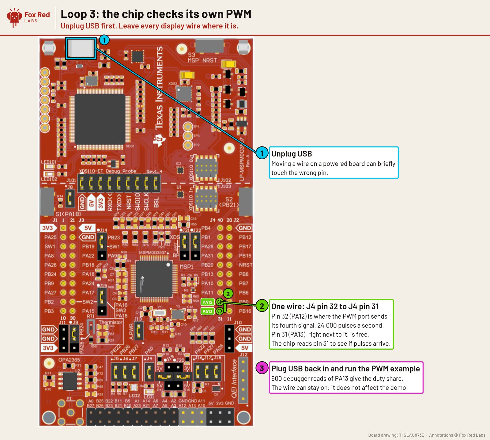
Pins are drawn on TI's board drawing; the source is in the repo next to the README. Open full size
Loop 3: the chip checks its own PWM
You need
- LP-MSPM0G3507 LaunchPad development kit: TI's 80 MHz Arm Cortex-M0+ board with 128 kB flash and 32 kB RAM, a built-in debugger, three buttons, two LEDs (one RGB) and light and temperature sensors.
- ELEGOO jumper wires (120-piece pack): Male and female breadboard wires for connecting anything to anything.
Wiring
- Unplug USB. Every display wire can stay where it is
- One wire from J4 pin 32 (PA12, PWM channel 4) to J4 pin 31 (PA13, read back as a plain input)
- Plug USB back in and run the PWM example; the program samples PA13 600 times
What was measured
- PA13 high in 88 of 600 samples: 14.7% plus or minus 2.8%, against 12.5% in the original STM32 example this was ported from
- Measures the share of time high, not the frequency; channels 1 to 3 not measured
Versions: MSPM0 SDK 2.11.00.07, TI Arm Clang 5.1.1, TI's migration skill; measured 2026-10-06.
Next: Measure channels 1 to 3 and the frequency with a timer capture instead of debugger reads.
How to repeat it: Jumper wires on the LP-MSPM0G3507: three loops to start. Errors and fixes: FAQ. Numbers from LP-MSPM0G3507 timer PWM notes.