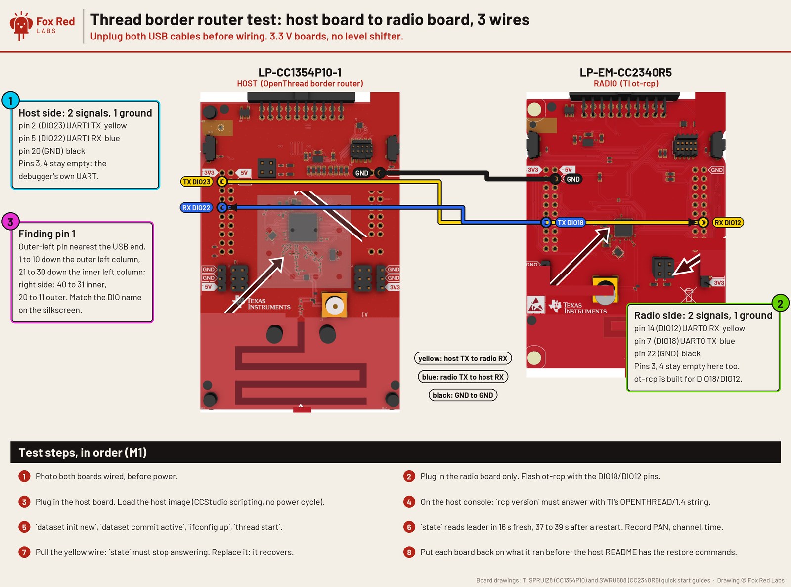
Pins are drawn on TI's board drawing; the source is in the repo next to the README. Open full size
Two boards, three wires: a Thread border router host and its radio
You need
- LP-CC1354P10-1 LaunchPad development kit: TI's sub-1 GHz plus 2.4 GHz radio board: Zigbee, Thread, Bluetooth and long-range sub-1 GHz.
- LP-EM-CC2340R5 LaunchPad development kit: TI's Bluetooth Low Energy and Zigbee board (CC2340R52 chip). Needs a separate XDS110 debugger to program it.
- ELEGOO jumper wires (120-piece pack): Male and female breadboard wires for connecting anything to anything.
Wiring
- Host CC1354P10-1 pin 2, DIO23, UART1 TX, to radio CC2340R5 pin 14, DIO12, UART0 RX
- Radio pin 7, DIO18, UART0 TX, to host pin 5, DIO22, UART1 RX
- Host pin 20 GND to radio pin 22 GND
- Both boards run 3.3 V, so no level shifter. Leave each board's debugger UART pins alone: host pins 3 and 4, radio pins 3 and 4
What was measured
- The host runs OpenThread with the CC2340R5 as its radio over the wire. It forms a network and is leader within 16 s of a fresh dataset (one check), 37 to 39 s after a restart
- The host image is 437.8 kB of code, 456.7 kB of flash with its initialized data. It needs 125.9 kB of RAM with logging compiled in. The wire runs at 921,600 baud
- Both signal wires were checked by driving each from one chip and reading it on the other through the two debuggers. A wire-less pin was the negative control. The ground wire was not driven, so shared ground is assumed
- Standby had to be turned off on the host or the link froze. Whether the radio link or the console dropped first is not known
Versions: SimpleLink F2 SDK 8.32 and F3 SDK 9.21.00.36, ot-ti, TI Arm Clang 5.1.1 and GCC 12.2; measured 2026-10-07.
Next: A second Thread radio so a device can join through the host and be pinged; then Wi-Fi on the host board with the CC35X1.
How to repeat it: border router host CC1354 notes. Errors and fixes: FAQ. Numbers from border router notes.